


As part of the design process, I need to find out how the digital inputs of the SCITS available to me function along with the inputs to the counter / timer unit that I will utilise to calibrate the timer I am building.
The counter / timer unit is fairly easy as the input impedance is selected with the channel setup menu. There are two options available, a 50Ohm and a 1MOhm input impedance. To limit the output current required by the timer, I will select to use the 1MOhm input when ever I am calibrating the timer.
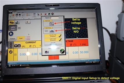
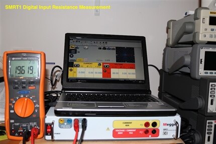
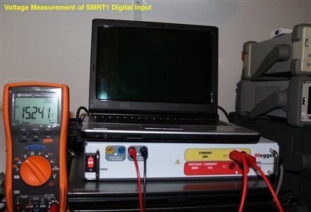
The Megger SMRT1 unit was the next to be tested. The manufacturer does not provide much information on the digital input. It does have the ability to work with either voltage present or voltage free contact on the relay with an input voltage between 5 and 300V AC or DC. I decided to try and measure the input resistance of the SMRT1 whilst it was energised with a multimeter set to ohms range. To do this the digital input of the SMRT1 needs to be configured to respond to a voltage applied to it and not its default state of a lot free contact when it outputs 15V to detect the contact closure.
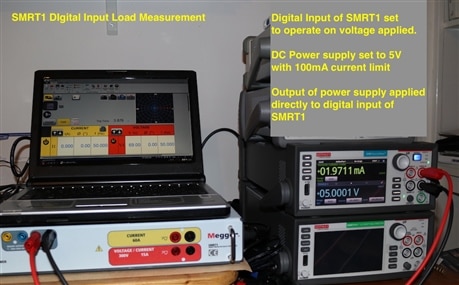
The digital input resistance measured with the ohmmeter was 19.6kOhms. A second check was made by supplying 5V into the digital input which gave a current of 1.97mA supplied into the SMRT1.
\
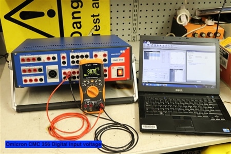
A similar set of tests were carried out on the other test set available to me.

This required a much lower input current of 10uA to enable the input at 5V.
Both these test sets should therefore be able to be driven by a TTL output. However, I do have one small concern. I did note during the tests that both units default to volt free contact configuration when first switched on. The SMRT unit puts out 15V and the CMC 356 puts out 8V. Both these voltage levels would cause damage to a TTL output.
I will have to be either very disciplined with setting up the timing tests, or I will have to look at how to provide some over voltage protection to the outputs.
A second issue, that ties in with the first, is that the SMRT unit needs a minimum of 5V to trigger the digital input. A TTL gate may struggle to supply this, the data sheets for some of the MCUs I have been reading gives their output voltage as 3.3V, acceptable for TTL compatibility, but not for triggering a SCITS.
It therefore may be prudent for me to tweak my design so that the output of the MCU drives a transistor or MOSFET. This may introduce a delay in the output that will affect the timing duration, but as long as it is consistent, I hope I will be able to cater for the delay within the program. However, I will have to provide some way to switch a potential as well, because the Keysight timer / counter only has potential free inputs and need an external voltage to drive it.
Top Comments