


What is a SCITS?
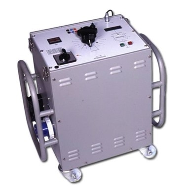
A SCITS is a Secondary Current Injection Test Set. I use them to test protection relays to show that they are operating within the manufacturer's specifications. They come in a multitude of types and sizes. Old style units were analogue design and basically consisted of an isolation transformer and a variac to adjust the output with. As time has gone more and more functionality has been added to the test sets and the modern sets produced today are usually digital versions driven by specialist software. Below is the layout of an old Foster SCITS100 injection test set that I first learned protection relay testing on.
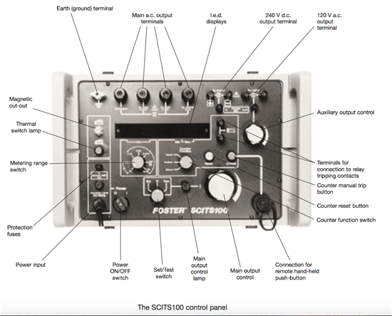
This type of test set offers single phase AC voltage and current across three ranges selected by changing the test leads to the required terminal up to a maximum voltage of 240V or a current of 100A. The test voltage / current is set manually using the main output control.
It also offers two auxiliary outputs for powering relays, a 240V DC output and a variable 120V AC output. Added to the test set is a single contact input that is wired to a volt free contact on the relay to record the operating times.
The test set must be manually set up first to deliver the required current or voltage for the test using the set mode. The test is conducted by then switching over to the test mode that enables the timer to control the test set.
Protection is fairly basic with a thermal cut-out for the internal transformer and fuse protection on the input. There is also a lock out function for the output, that switches it off if the test set looses power or is turned off at the main switch, to prevent inadvertent output on the terminals. This is reset by turning the main output control back to zero.
The control is quite coarse as the lowest current range is 10A, and to carry out creep tests at low current below 1A for certain relays, high power variable resistors are used in series with the output to increase the sensitivity of the main output control.
Compare this to the latest test set offering from Omicron below. This is a computer driven package with special application software for testing various different types of relays. This test set has two sets of three phase AC voltage outputs and a single set of AC current outputs. These outputs can be wired in various series and parallel combinations to increase the current or voltage output capability. A variable auxiliary DC output is available to provide power to relays under test. There are a total of six binary inputs that can be configured as voltage free or voltage dependent contacts, allowing more contacts form the relay to be monitored at anyone time. There are also four binary outputs that can be utilised to provide control functions for relays under tests. This latest package from Omicron weighs less than 9kg (19lbs)in comparison to the old Foster SCITS100 that weighed 41kg (90lbs).
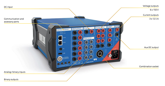
Safety is also improved with the more modern test sets. The outputs are monitored and will not be activated unless the test set senses a circuit is attached to the relevant outputs. Electronic overloads are supplied to monitor each output.
Control of the test sets through the software increases setting accuracy and efficiency as the required values are typed into the various parameters and then the set activated to apply them. Unlike the older test sets where ramping the current up or down was controlled manually by the operator turning the main output control, the software provides various ramping functions that are applied automatically once the start and stop points, step value and rate of change are entered. Naturally, these setups can be saved and called back up again when required. Further more, by utilising software, results can be transferred to an electronic report instead of recording them manually using paper and pen.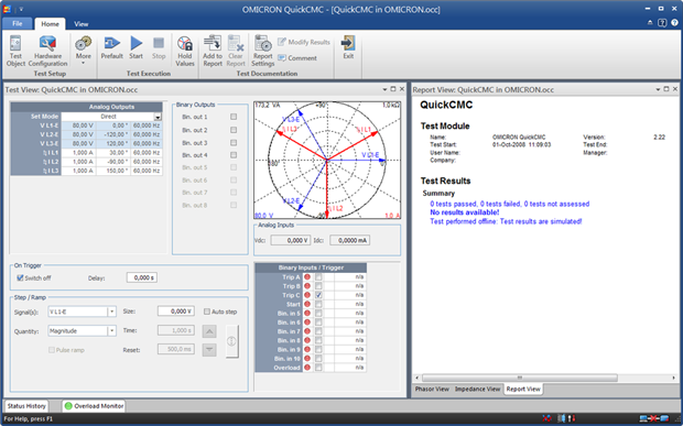
As can be seen, both test sets have the same basic functionality, a modern single phase test set will produce voltage up to circa 300V and current up to 60A and will have a digital input as minimum with a built in timer. Three phase test sets can produce up to 600V and 180A by reconfiguration of the multiple outputs adding even further versatility.
How is a SCITS used?
Voltage and currents from a SCITS are injected directly into the protection relays to test their functionality. In this way lower voltage and currents are used as the secondary injection by passes the current and voltage transformers that connect the protection relays to the apparatus they are protecting.
The alternative to secondary injection testing is primary injection testing. To do this access to the bus bars is required so that voltages and currents can be applied to the primary circuits.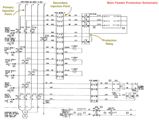
As seen in the diagram on the right, the protection relay (50/51N) takes current from 1600:1A CTs. To carry out secondary testing, I only need to inject multiples of 1A to get the relay to operate. For primary injection testing, I would need a test set to deliver 1600A, just to get 1A into the relay. This is much more time consuming and hazardous to carry out.
A T&R PCU2 (left) would be a possible primary injection set utilised to carry out that kind of a test. It is capable of injecting 3000A continuously and up to 12000A on an intermittent basis. Coupled with this, must be test leads capable of carrying such high currents for short durations. It must also be noted that the test set itself weighs 115kg (254lbs), which produces its own challenge to get it into a switch room accessed via a set of stairs.
Why it is important to test
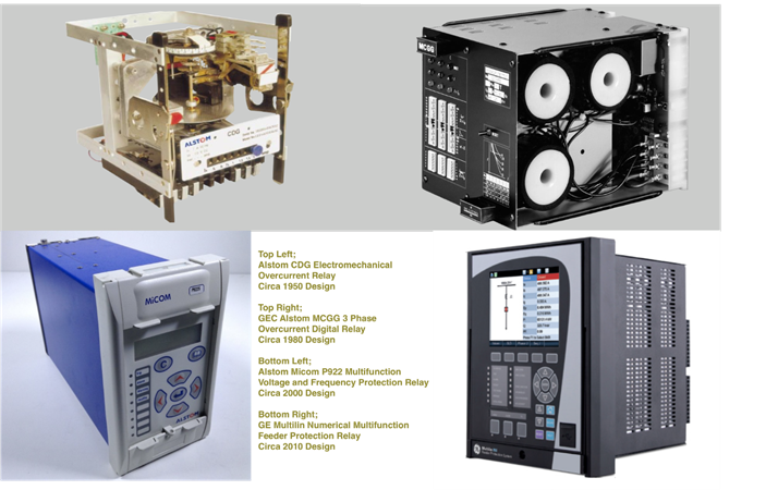
Protection relays have also evolved through the years moving from electromechanical devices with individual functions through digitised technology up to modern numerical protection offering multiple types of protection within one package along with load monitoring and disturbance and fault recording functions in networked systems that can be accessed remotely.
Old style electromechanical relays would need regular operational checks to ensure that the mechanical elements of the relays were still operating correctly. These types of relays are more susceptible to damage from the currents they are subjected to during fault conditions. Digital relays are less susceptible to fault current damage but the types of components utilised are susceptible to drift over time and the testing required does not need to be as regular as that required for an electromechanical relay.
Numerical relays are the most reliable protection relays available today. They also contain self monitoring systems and watchdogs to generate alarms if relay faults become apparent. However, they cannot test their own pickup settings and trip times. Testing of numerical relays is much less onerous than digital and electromechanical relays. It must be remembered that as a single multifunctional numerical relay can be used to replace multiple digital or electromechanical relays, a failure would have a much wider impact on a protection system, that could leave multiple elements unprotected.
Standard feeder protection relays operate on timing curves to IEC 60255 standard. This allows for discrimination to be created along a supply feed to minimise the disruption to an electrical supply during a fault. This discrimination is created by appropriate selection of the pickup level of the relay as well as the trip delay. Trip curves for protection relays can also be compared to damage curves for electrical apparatus such as supply transformers and cables. Ensuring that the protection relay will trip the breaker to a transformer before the fault energy flowing can cause damage to the winding is fundamental to the correct operation of a protection system. For both of these protection methods, a low fault current will be allowed to flow for a longer period of time than higher fault currents to allow faults to be cleared by the closest protection relay in an attempt to minimise the disruption of supplies.
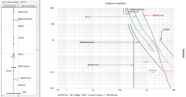 A typical discrimination plot is shown on the left that also includes the damage curves for the two cables (M1002 and P3001) and the transformer BFT31.
The HV cable M1002, is protected by BBA02-Fuse as it is fully to the right of the curve for BBA02-Fuse. However the fuse will not provide full protection for the LV cable P3001 or the transformer BFT31 whose damage curves partially sit to the left of BBA02-Fuse curve.
For the transformer and the LV cable BBA02-MCGG protection relay will provide complete protection.
Although the curve for BFG02-P141 sits the furthest to the left on the discrimination plot, it will only provide protection for the previous items if the fault occurs on the BFG bus or beyond.
The graph clearly shows the discrimination between the various protective devices so that the ones further down stream on the line diagram should operate before the ones further upstream.
More complex protection systems operate on definite time settings. Instead of having a trip curve to follow, relays are set to allow faults to be present for a maximum permissible time. Under and over voltage protection systems are an example of this as they will allow the fault to continue for a number of seconds in an attempt to allow the electrical system to recover before tripping. Some protection systems such as differential protection are set to clear a fault as quickly as possible should the relay pickup setting be exceeded by the current. These types of systems will operate within milliseconds.
It is therefore important that the correct operation of these aspects of the relays is proven during installation and commissioning and as routine maintenance during the operational life of the protection system. This is the job of primary and secondary injection test sets.
The project
When I go to site to test a protection system, after setting up the test apparatus, I like to run a few basic tests to show that the setup is functioning correctly and that nothing has been damaged in transit. When testing complex protection systems that protect high voltage apparatus worth a substantial amount of money, I regard this basic testing as good practice. Testing the voltage and the current is easy to do with a multimeter, but I currently have no way of testing the timing function of the test set.
So, my little project is to attempt to build a portable timer module so that I can validate the timing function of a SCITS when I am out on site.
For the next blog, I will show a SCITS being utilised on some protection relays before I move onto the actual design and build project.
Top Comments
-

mcb1
-
Cancel
-
Vote Up
+2
Vote Down
-
-
Sign in to reply
-
More
-
Cancel
Comment-

mcb1
-
Cancel
-
Vote Up
+2
Vote Down
-
-
Sign in to reply
-
More
-
Cancel
Children