


As I previously wrote, I was not happy with the performance of a SPI-based LCD screen. The framerate was much lower than I expected. I happened to have some 4.3" TFT panels with 40 pin connectors. The problem is that I don't have their original datasheet. It took some trial and error, but I eventually found a combination of settings that worked on my screen.
Other than the random datasheets, I found these resources very helpful:
- Robert Ely's blog post "Let's add a direct cheap screen to the Raspberry Pi B+"
- Adafruit's DPI Display Kippah directions have some more information
- Note, I do not think the settings used for the 4.3" screen are correct. They do not match the datasheets for the 4.3" panel that Adafruit sells and caused quite a bit of flicker on my panel. Perhaps it was wiring related?
- Raspberry Pi's DPI Instructions
- of course, Ben's No HDMI Pi Video
If you plan to direct drive your LCD, it is entirely possible. You need to have patience though. It is not a "plug and play" activity.

The key to directly driving an LCD with a Pi is "DPI" mode. You clock-in 6-8 bist of data for each of the three colors Red, Green, and Blue. It is a parallel bus which means it is highly efficient, especially compared to SPI. Since this was my first attempt, I stuck with some standard header pin cables between the Pi and the Adafruit TFT breakout board. The bad news is that the DPI spec appears to run around 28 MHz. The good news is that my screen's rating is between 7 and 12. The cables I used were long enough that 6.4 MHz was about the fastest I could drive.
Here's a couple of things I learned that I did not find in any of the above resources.
- DPI Clock
- Crosstalk is an issue
- Use HEX in the config.txt
- 22-bit vs. 24-bit
- Tips
DPI Clock
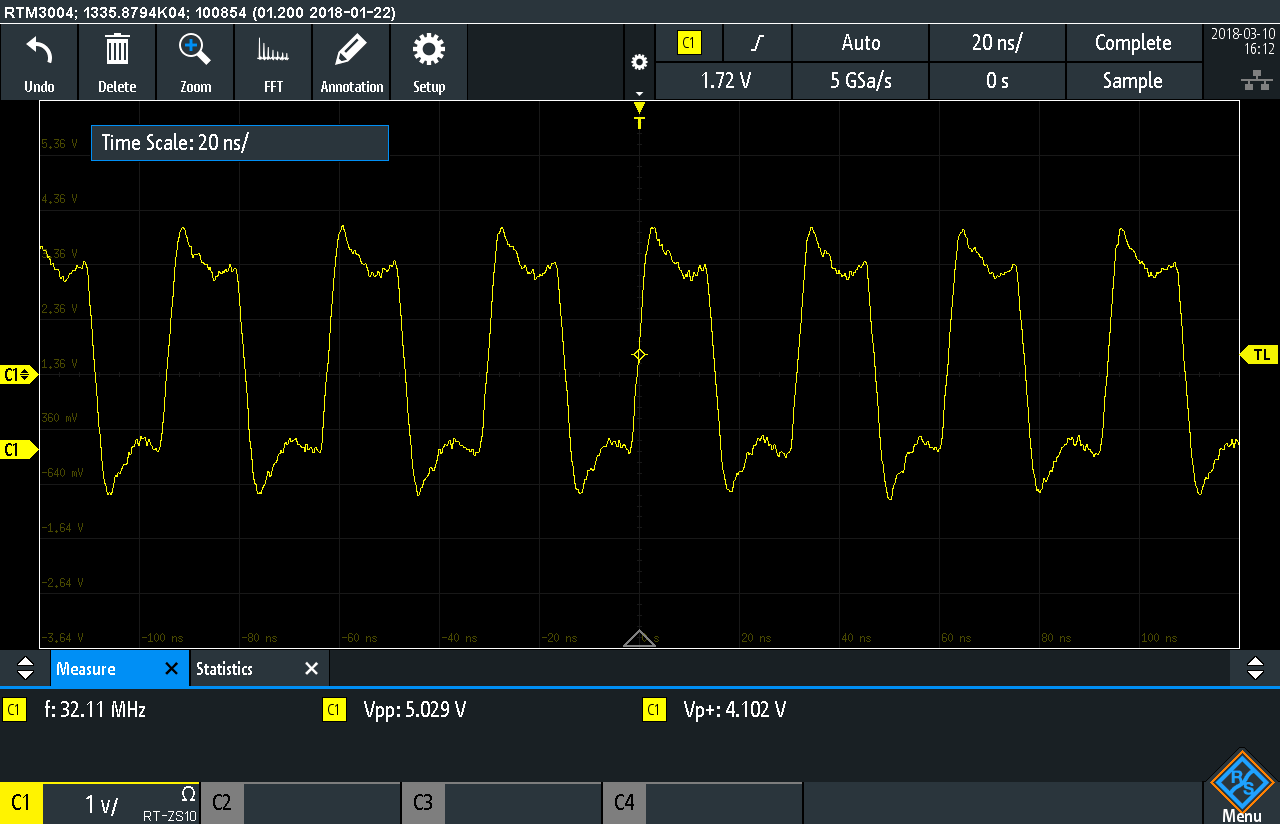
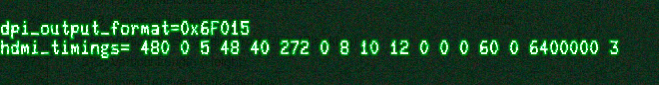
The Pi cannot generate arbitrary clock speeds. Most resources are using 32 MHz in the config.txt's HDMI timing line. In my case, that was WAY too fast. The datasheets I found for 4.3" LCDs online all had a typical clock rate of 9 MHz. However, changing the line to 9000000 resulted in no clock. The Pi can only generate clock speeds such as 4.8, 6.4, 9.6, and 32 MHz. Other speeds might be possible. These were the ones I generated and verified with my oscilloscope. If you are using long wires as I did, you need to slow down well below 9 MHz.
Currently, I am set up for 6.4 MHz, which is out of spec for my panel. However, until I have a new wiring harness, the signal integrity just does not hold up at 9.6 MHz.
Crosstalk is an issue
Even around 10 MHz, there is quite a bit of potential for crosstalk. The bits on the Pi's GPIO header are ALL OVER the place. You have to be very careful about how you route your wires. For that reason, I created a PCB to swizzle the signals. (After I verify this works correctly, I will post links to the design files.)
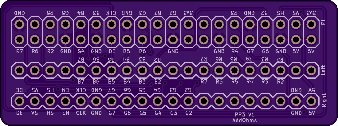
I minimized crossing signals when possible. I intend to solder to the GPIO header of the Pi and then use a ribbon cable to solder to the 40-pin breakout board. This board is a risk. If I introduced crosstalk issues, I probably wouldn't be able to fix them without re-spinning the board. If I had more time available, I would have made this a 4 layer board with the top and bottom layers acting as a ground shield. However, we will see how it turns out!
Use HEX in the config.txt
When setting up the Pi's DPI registers, you can enter values in either decimal or hex. In Ben's video, I noticed he was using HEX. Using HEX makes iterating settings much easier. However, don't make the mistake I did, which cost me about 2 hours of pointless troubleshooting.
19-bit vs. 20-bit
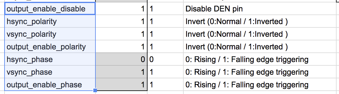
Ely's made a spreadsheet to manipulate the DPI registers. It is a fantastic tool, even if it does convert the values to decimal instead of HEX. (I ended up creating columns to make binary nibble groups that I converted to HEX values.) Here's where I made my mistake. On the spreadsheet, rows 15-12 represent the MSB of the HEX string. While they do represent the MSB, the register is only 19-bits wide!
So for example, I was making my MSD (most significant digit) 0xF that was making the MSD 0x7. (1111 vs. 0111). So in my spreadsheet, I color coded the values. After that, it was easier to change the dpi_output_format register.
Tips
In my final video, I plan to talk about how to iterate through settings. (I do not plan to cover the above topics, at least, not right now.) One pain in the butt is that each time you make a DPI change, you have to reboot the Pi. That gets old quick. In my testing, what I found is that when the screen is white something is too fast and when it is off something is too slow. So for example, when running at 32 MHz, I usually got a white screen with ghosted lines. While at slower speeds, I had a black screen with ghosted images. If you are confident you have wired the screen up correctly, I would first focus on determining the polarity of V- and H-sync. Even with all of the other timings wrong, you will see something reasonable an image on the screen. After that, it is iterate, iterate, iterate.
This week
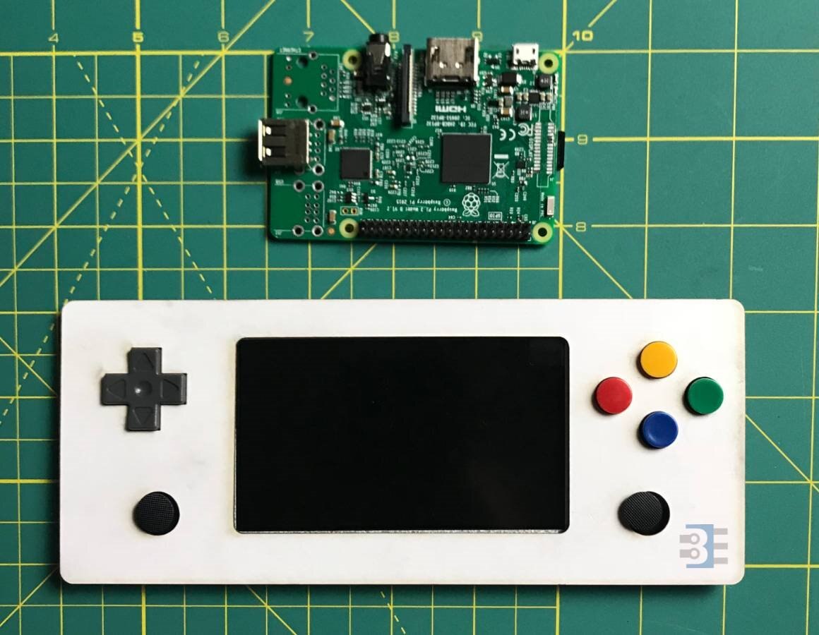
Now that I know how to drive the screen, I am back to working on the enclosure. I am assembling all of the pieces into Fusion 360. I have laser cut a mock-up of my front panel only to realize I missed something.
Top Comments