


The first application that the component list suggests is for a forward-reverse starter that allows the start of a motor for both forward and reverse operation.
For each direction we need a contactor, a start and a stop button.
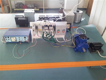
In order to have a testing system, we start with the system presented in the first RoadTest. I have added a circuit breaker, an induction motor and the corresponding wiring cables for forward and reverse starting. The power lines are connected to the same input terminals of the two contactors. At the output of the contactors, the second contactor has two phases switched in order to obtain the reversing operation of the motor which, in this test, is connected in a star configuration.
In the next steps we will program the Easy controller in order to obtain the forward and reverse starter operation.
I have installed the EasySoft Pro v.6.90 that came with the kit and also the driver for the EU4A-RJ45-USB-CAB1 cable that will be used for the communication between the PC and the Easy controller. Usually there are no problems in installing the software. I had a small problem because my laptop has no CD/DVD unit. Therefore, I used another computer to create images of the two CDs and then put the images on my laptop. I then used Daemon Tools Lite to emulate a CD unit able to read the images and continue the installation of the software as if it were from CD.
As we start EasySoft Pro software we must have in mind the fact that we do not program only the controller but the entire SWD system which is made of several components that are connected together and which during operation communicate over the flat green cable. Therefore, what we have to do is first describe the SWD system and after that, write the program for it.
In system specification step we have to specify what controller we are using and which SWD components are also part of our system.
This task can be done using a very easy and intuitive - pick, drag and drop and configure (PDDC) – procedure. We start by selecting the Project tab, where in left window we have the list of possible controllers to choose from. In our case we must select the EASY802-DC-SWD controller, and this can be easily done because the controllers are grouped by families (EASY 400, 500… 800) and for each controller a picture of the front side is displayed.
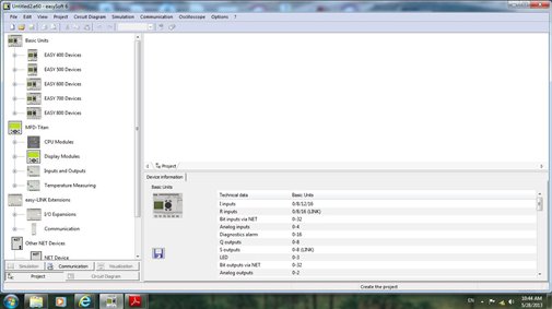
Once identified, the controller is selected in the left window, dragged and dropped in the project window. Bellow this window is the configuration window that allows us to configure different features of the controller.
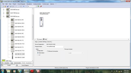
We will input in the Program Name field the text “ForwardReverse” as the name of the program we will create.
We can configure some of the programming elements to be retentive, and also to set different security levels using a password. You can use this if you want to sell the system but not the application program details.
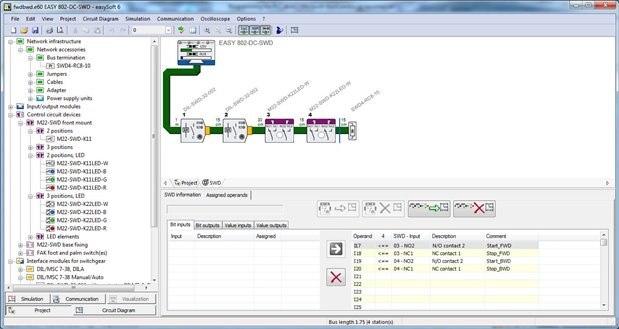
Next step is to describe SWD system in the SWD tab. The same PDDC procedure must be used to create the system. The left window contains the SWD devices that can be used to create a SWD system, the devices being grouped on several categories. The right up window is where we drop the devices to create the SWD system. The controller is already there, we continue to add the other devices. The diagram must match the real system in type and number of devices and the order in which these devices are connected.
We start by adding the first contactor interface module (DIL-SWD-32-002). When we drop it in the right up window the connection with the green cable is automatically added between the controller and the added device. The same happens when the other devices are added to the SWD system. You can add a new device either before or after any device that is already present in the diagram. At the end of the cable a bus termination (SWD4-RC8-10) is automatically added by the program or must be added by the programmer. Any green flat cable connection is added with a default length of 2m for the first connection (controller –device) and 10 cm for the others (device – device). These connections must be adjusted to reflect the real lengths of the cables in the system.
Once a device is added to the system it can be configured in the right lower window. In general, the device that we want to configure must first be selected in the upper window.
If a device is selected, we can also get the datasheet of the device by clicking the right mouse button and selecting “Datasheet”. A browser window opens the datasheet from datasheet.moeller.net website. This is good and useful. But what if internet connection is not available? I would love to have the datasheets of the devices I use in my system locally available. The software should first look if the datasheet is not available on the local computer in a specified datasheet folder then, if not, go on internet, bring the datasheet and save it locally in that folder.
I prefer to create the system first, by dropping all the devices of the SWD system and after that, to configure them one after another.
Configuration depends on the device type. For example, in the case of interface module we can specify which type of contactor the module will interface. Other devices have more or less parameters to configure.
Another important task during configuration of the module is to assign operands to the resources of the device. These can be input bits (related to NO, NC contacts), output bits (related to contactor coils or signaling devices) or other related to diagnosis.
I have made the following assignments
Inputs | Device resource | Comment |
I17 | NO (M22-SWD-K22LED-W #1) | Start_FWD |
I18 | NC (M22-SWD-K22LED-W #1) | Stop_FWD |
I19 | NO (M22-SWD-K22LED-W #2) | Start_BWD |
I20 | NC (M22-SWD-K22LED-W #2) | Stop_BWD |
Outputs |
|
|
Q17 | Contactor actuation (DIL-SWD-32-002 #1) | FWD |
Q18 | Contactor actuation (DIL-SWD-32-002 #2) | BWD |
Q19 | LED white (M22-SWD-K22LED-W #1) | LED_FWD |
Q20 | LED white (M22-SWD-K22LED-W #2) | LED_BWD |
The comments are in fact the symbolic names given to different programming elements in the ladder diagram. These comments will appear in the ladder diagram above the programming elements and will make the diagram easier to read and understand (of course if good names are chosen).
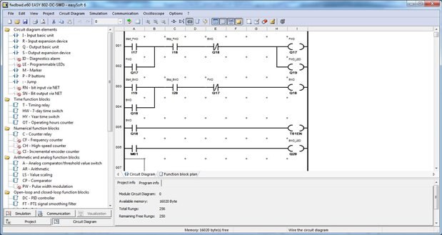
Next step is creating the circuit (ladder) diagram by selecting the “Circuit diagram” tab and using the assignments from the table before. In the left window we find the programming elements that can be used in the ladder diagram. The right window is hosts the ladder diagram.
Before creating the ladder diagram we must be aware of Easy controller family programming limitations such as that each line of the ladder diagram can contain only 4 contacts and one coil. This helps you to understand where you can place a contact or coil element and where not. Read the programming manual or the online help for more details.
The ladder diagram can be created using the same PDDC procedure as for creating the SWD system. We select the programming element in the left, drag it to the right window and drop it in the desired (and valid) position. Then the element can be configured based on which type of element it is.
I normally like to be as much productive as possible. Therefore, when evaluating a software tool for programming PLCs, I look in the manual or online help to see if the software is supporting productivity in creating the ladder diagram. This means the possibility to input the ladder diagram using only the keyboard by typing different keys or key combinations.
I was very happy to find that EasySoft Pro supports this productivity feature. I was also happy to see that inputting the ladder diagram by the keyboard is very simple and the keys are very intuitive (i for inputs, q for coils, m for markers, etc), NO can be switched to NC only by pressing the space key etc.
The entire list of keys can be found in the “Keys and Key Combinations in the Programming Software” section of the online manual.
The ladder diagram I created is a classic one for a forward-reverse starter with one start and one stop button for each direction, with a sealing contact in parallel with each start button and with interlocks that prevent powering the motor for opposite directions operation at the same time.
Taking advantage of the LED available for each M22-SWD-K22LED-W device, I added some circuitry so that the LED for the forward direction is lighted when motor rotates forward while the LED for the backward direction is lighted intermittently when motor rotates backwards. Thus we have a visual confirmation of motor direction of operation.
For this purpose, the FWD_LED is in parallel with FWD coil while for the BWD_LED I had to use a relay that would alternately energize and de-energize with a certain frequency. In the programming software for other PLCs I would find this type of relay as a separate type. In the case of EASY controllers this is part of the timing relay group. Thus, a contact of the BWD coil energizes the T1 timing relay whose associated marker M1 energizes the BWD_LED. The association is made when configuring the T1 timing relay. The configuration implies selection of T1 mode as “Flashing”, Function Block Output as Marker byte M1, and Time Range with 1 s resolution.
The resulting ladder diagram is given in figure bellow.
Before loading the ladder diagram in the controller memory and test its operation is good to do a simulation of the circuit. EasySoft Pro allows that by selecting the Simulation tab.
In the left window we can see and modify the status of inputs, we can change the parameters of the simulation cycle, include brake points for debugging or we can choose the programming elements to be displayed. We can also see and modify the status of SWD devices inputs.
In right upper window we have the ladder diagram whose active paths and energized elements turn to red, making possible to visualize the diagram operation (see figure bellow).
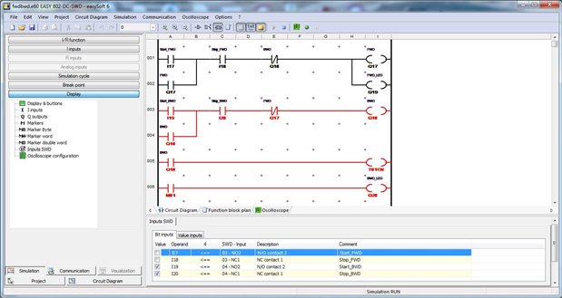
The simulation indicated that the ladder diagram is OK so I went to the next step which is verifying the operation of the control on the real system.
In order to transfer the program to the controller, the communication between the PC and the PLC must be established. The EU4A-RJ45-USB-CAB1 cable must be connected both to one of the PC USB ports and to the corresponding port on the Easy controller.
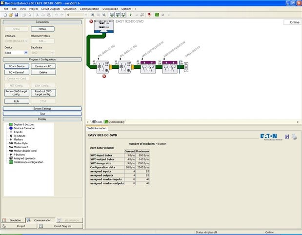
We then select the communication tab where several operations implying PC-PLC communication can be issued: connection, program transfer to/from PLC, SWD configuration transfer to/from PLC, verification that program in the PC is the same with the one in the controller etc.
In order to communicate with the controller, we must select the Communication tab and push the Connection button. This opens the Communication configuration group where we can establish which port we use to communicate and baud rate.
When we push the Online button, the software reads the SWD configuration from the device in order to have the real configuration of the system and not one that was saved on the computer and can be different from the real situation.
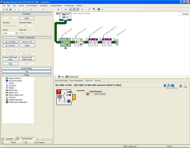
After I have load the SWD system configuration to controller memory, I tested to see what happens if I disconnect one of the devices of the SWD system (thus modifying its configuration). I powered off the SWD system, I disconnected one DIL-SWD-32-02 contactor module,then I powered the system on.
The software sensed that I have powered off the system and displayed an error message with a list of possible causes for the error. Clicking OK button of the message put the connection in Offline mode. When pushing Online button again, the software read the SWD configuration from the SWD system and indicates that something is wrong in the SWD system. The SWD LED in the SWD->Device Information tab and on the Easy controllers were both red and were flashing.
In the upper window we can see the device that causes the problem. When selecting the contactor module icon, in the In the upper window we can see the device that causes the problem. When selecting the contactor module icon, in the Diagnostic tab we can see that the device is missing. Restoring the initial configuration, everything gets back to normal.
Pressing Program /Configuration button we get access to a set of buttons that allows us to transfer the program to controller memory, read program from controller memory, verify if program in PC memory is identical with the one in the controller memory and also we can read SWD configuration from SWD system or renew the SWD system configuration.
Run and Stop buttons put the controller in run and stop mode respectively. The safe modification of the program in controller memory is implemented so, if we try to make the change when it is running, we are alerted that the controller is in run mode and we are asked permission to stop the controller first. I we agree, the controller is stopped and then the software loads the new program. After loading the program, the controller is put again into the run mode.
The Display button gives us the possibility to display the status of programming elements of the system.
The EASY802-DC-SWD unit has no display. Nevertheless, EasySoft Pro emulates a user interface (display and pushbutton) similar to those available on the normal Easy controllers. We can use this display the same way we would do with a real one to monitor inputs and outputs of the system, create or modify the circuit diagram, monitor controller operation or change the controller parameters.
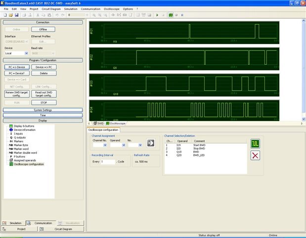
For those who want to see how signals are changing in the system, a virtual oscilloscope is available also in the Display group. We must first configure the oscilloscope by choosing the signals we want to visualize in a waveform manner. I have selected the signals for START_BWD, STOP_BWD, BWD and LED_BWD. The recording is started using Oscilloscope recording on button on the toolbar and stopped using Oscilloscope recording button of button.
At the end, I connected the power supply for the motor, put the controller into run mode and tested the system.