From the beginning I was very excited to test the Smartwire-DT kit from Eaton. I have heard about the Smartwire technology some years ago, when first developed by Moeller (now part of Eaton), but never have to opportunity to test it.
Working on some projects in industrial control based on PLCs, I was confronted with the wiring problem involved by this kind of systems. Every device connected to the PLC (sensors, buttons, switches etc) need two to three wires resulting in several bunches of wires, difficult to wire and debug.
I have started this Roadtest having in mind to use the kit for creating a laboratory work for my PLC course. The idea was to show to students on one hand, how easy it to do the wiring when using Smartwire-DT technology and on the other hand an implementation of industrial communication.
Usually students find in the lab the control system already wired. The time allocated to the lab work is not enough for the students to cover the lab work topics, conceive the control diagram, wiring PLC modules, sensors and switching devices, simulate the PLC application, load the application in the PLC memory and test the working application. Using the Smartwire-DT technology the wiring would take only 5 minutes and you must not worry that the students can make wrong connections. That is true also for the technicians that would do the wiring for a real application.
This is what I get in the box:
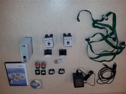
1 x Easy802 programmable relay with SmartWire-DT
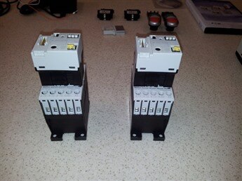
2 x Contactors
2 x Start-Stop illuminated doube pushbuttons
2 x SmartWire-Dt pushbutton LED modules
1 x SmartWire-DT flat cable assembly with device and end connectors
1 x SmartWire-DT terminating resistor
1 x EasySoft programming software v.6.90
1 x Programming cable
1 x AC Power supply
1 x Pocket screwdriver
1 x Getting started brochure
When I first tested the kit I tried to follow the step-by-step procedure in the Getting started brochure (received with the kit), so all the devices were assembled on a table.
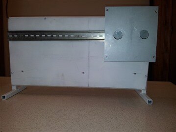
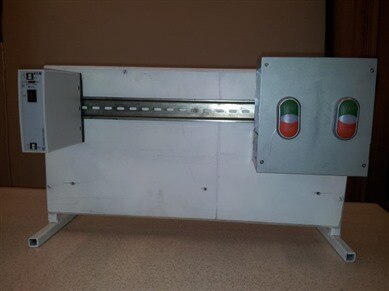
For a laboratory work this kind of assembly is not very handy and not very secure.Ttherefore, I have chosen to use a small vertical panel with a DIN rail on which the devices can be mounted just as they would be inside a control panel.
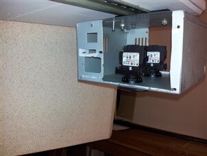
I have several such panels for student works settings. I unmounted the existing devices from one of them making place for the devices of the SmartWire kit.
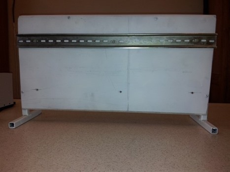
The next step was to find the way in which all the devices in the kit could be mounted on the panel so they can be visible, accessible and connected easily (what must be demonstrated).
Usually the PLC, the contactors, the starters and other such devices are mounted inside the control panel while, the buttons and lamps are mounted on the front door of the control panel. I had no front door for my panel therefore, I had to find another way to mount the two pushbutton modules.
My quick solution was to use the case from a broken computer power supply. I have drilled two holes for mounting the pushbuttons and also cut the lateral parts so the cable could pass from one side to the other and provide enough space for easily doing the connection to the pushbutton LED modules.
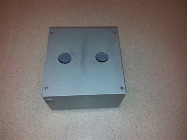
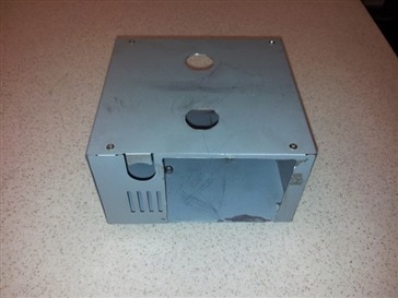
In order to be mounted simply on the DIN rail, to this made pushbutton case I have attached the mounting part from an old contactor, making the case, DIN rail compatible.
Other solutions? I am waiting for suggestions.
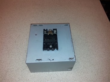
In the next step I mounted the Start-Stop pushbuttons, and assembled the pushbutton LED modules.

As I tested, and can be seen in the figure, the pushbutton can be mounted easily on the pushbutton case and there is enough space to introduce the cable and make the connections to the pushbutton LED modules.
Next steps were to mount the other devices of the kit. Even though the system permit easy connection of the devices, care must be taken because the connections must be made in one way so the connection would look nice with no torsions of the cable.
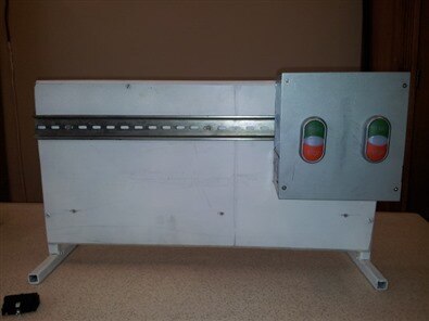
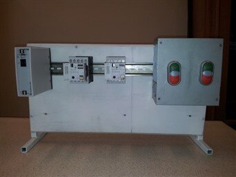
The order I have chosen, from left to right, was: the Easy relay, the two contactors and the two buttons.
Before mounting the contactors, the SmartWire-DT contactor modules were attached so they can be controlled and monitor by the Easy relay.
Next step was to make the power connection to the Easy relay. Unfortunately the AC power adapter supplied with the kit was of no use because it was built for US network (120 V input voltage at 60Hz) frequency) and not for European network (240 V input voltage at 50 Hz).
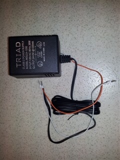
Most of the AC power supplies available these days are built so they can work on both networks (100-240 V input voltage at 50-60 Hz). Therefore I didn’t think to ask the RoadTest organizers what kind of power supply they will provide and request the right one. Next time I should be more careful. So, if anyone wants to make an exchange, I can give one US adapter and expect to receive one Europe compatible adapter.
The conclusion was that I have to use another power supply that could supply a 24 V DC voltage at 1.2 A current.

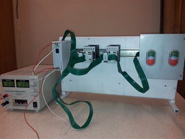
Last part was making the connection using the SmartWire-DT flat cable assembly provided with the kit with the SmartWire-DT terminating resistor connected at the end of the cable.
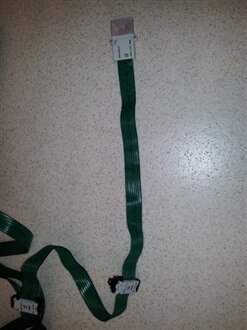
The wiring was done starting from the Easy relay and continuing by successively connecting the two contactors.
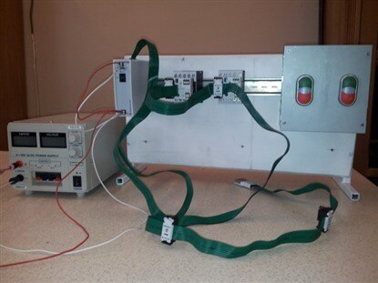
At the end were connected the pushbuttons. The result is given bellow.
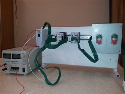
The power supply was powered on, and the system ready to be configured. The application was to be written and loaded to the Easy relay memory. But this will be described in another post.