element14 Community
element14 Community
    Register Log In
  • Site
  • Search
  • Log In Register
  • Community Hub
    Community Hub
    • What's New on element14
    • Feedback and Support
    • Benefits of Membership
    • Personal Blogs
    • Members Area
    • Achievement Levels
  • Learn
    Learn
    • Ask an Expert
    • eBooks
    • element14 presents
    • Learning Center
    • Tech Spotlight
    • STEM Academy
    • Webinars, Training and Events
    • Learning Groups
  • Technologies
    Technologies
    • 3D Printing
    • FPGA
    • Industrial Automation
    • Internet of Things
    • Power & Energy
    • Sensors
    • Technology Groups
  • Challenges & Projects
    Challenges & Projects
    • Design Challenges
    • element14 presents Projects
    • Project14
    • Arduino Projects
    • Raspberry Pi Projects
    • Project Groups
  • Products
    Products
    • Arduino
    • Avnet Boards Community
    • Dev Tools
    • Manufacturers
    • Multicomp Pro
    • Product Groups
    • Raspberry Pi
    • RoadTests & Reviews
  • Store
    Store
    • Visit Your Store
    • Choose another store...
      • Europe
      •  Austria (German)
      •  Belgium (Dutch, French)
      •  Bulgaria (Bulgarian)
      •  Czech Republic (Czech)
      •  Denmark (Danish)
      •  Estonia (Estonian)
      •  Finland (Finnish)
      •  France (French)
      •  Germany (German)
      •  Hungary (Hungarian)
      •  Ireland
      •  Israel
      •  Italy (Italian)
      •  Latvia (Latvian)
      •  
      •  Lithuania (Lithuanian)
      •  Netherlands (Dutch)
      •  Norway (Norwegian)
      •  Poland (Polish)
      •  Portugal (Portuguese)
      •  Romania (Romanian)
      •  Russia (Russian)
      •  Slovakia (Slovak)
      •  Slovenia (Slovenian)
      •  Spain (Spanish)
      •  Sweden (Swedish)
      •  Switzerland(German, French)
      •  Turkey (Turkish)
      •  United Kingdom
      • Asia Pacific
      •  Australia
      •  China
      •  Hong Kong
      •  India
      •  Korea (Korean)
      •  Malaysia
      •  New Zealand
      •  Philippines
      •  Singapore
      •  Taiwan
      •  Thailand (Thai)
      • Americas
      •  Brazil (Portuguese)
      •  Canada
      •  Mexico (Spanish)
      •  United States
      Can't find the country/region you're looking for? Visit our export site or find a local distributor.
  • Translate
  • Profile
  • Settings
Personal Blogs
  • Community Hub
  • More
Personal Blogs
Legacy Personal Blogs Switch Mode Power Supply from a SX-64
  • Blog
  • Documents
  • Mentions
  • Sub-Groups
  • Tags
  • More
  • Cancel
  • New
  • Share
  • More
  • Cancel
Group Actions
  • Group RSS
  • More
  • Cancel
Engagement
  • Author Author: ajkatz83
  • Date Created: 13 Feb 2018 5:39 PM Date Created
  • Views 1403 views
  • Likes 4 likes
  • Comments 10 comments
  • sx-64
  • commodore
  • commodore_64
  • commodore machines
  • switch mode power supplies
Related
Recommended

Switch Mode Power Supply from a SX-64

ajkatz83
ajkatz83
13 Feb 2018

The Backstory

Recently I had become involved with this b-bit revolution that has been going on. I remember, that perhaps the first computer I had before getting the IBM PS/2 model 70 was a Commodore SX-64, and man it did everything! From the dot matrix printing to programming of certain radios of Midland and Maxon to actual programming of the old cellular from GTE Mobilenet, that Commodore surely did quite a lot! Did I mention I loved Zaxxon an Impossible Mission that were made for that system?


In the later 2000's I had sold it off for what I thought to be a considerable amount of money, games an accessories all, and figured time and technology needs to move on, and for me that was the end of the Commodore.....well....so I thought....


Stumbling upon the local gaming convention here in Cleveland an as well The 8-bit Guy, I was surprised to see a retro revolution with 8-bit computing and how it's been re-innovated to do more than it did 36 years ago--in seeing and knowing that I was hooked and had to find a machine again that I sold decades earlier. I had found one on Amazon Marketplace and it looked to be pristine--it was an unbelievable find (even the original keyboard cable)--so I went ahead to purchase it, only to know I should have asked one question; was this system modified in any way? Sadly, I had to open her open to find a mess inside.


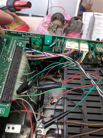
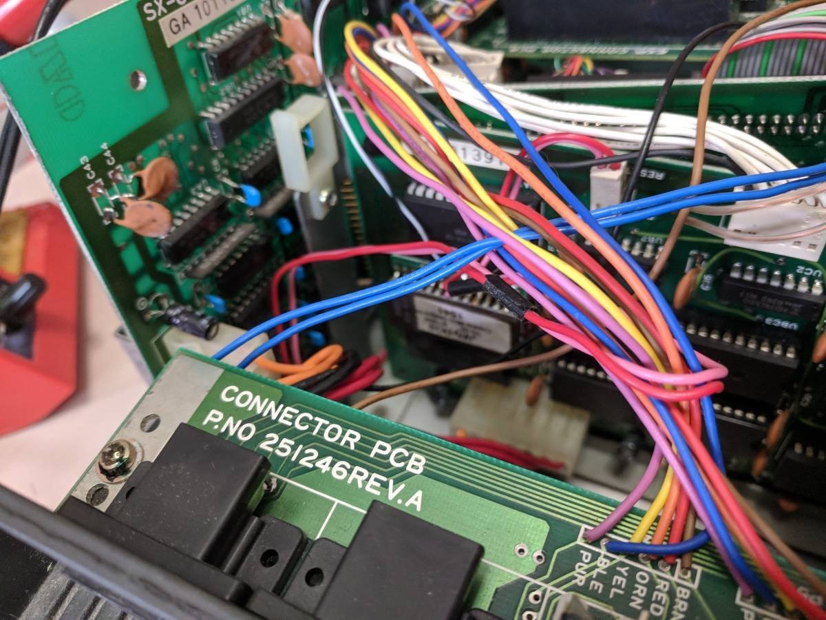
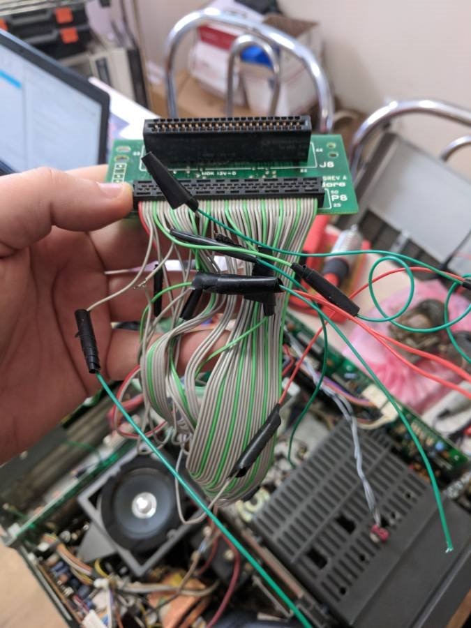
Don't get me wrong it worked for a time when I got it, but it was riddled with toggle switches in its storage compartment, only for powering on and off the selected devices within the machine, and then one for JIffyDOS and the standard pre-loaded BASIC. The other thing I notice was that there were bare wire splicing covered loosely in electrical tape that had been melted away by the heat of the machine; I was surprised that nothing had shorted out from the exposed bare wire, especially near the CRT. I was not happy what I was seeing, since the expansion cable was torn to bits for these toggle switches and the sloppy splicing.

imageimageimageimageimage


After a few weeks of have it here, I was going to use my SD2IEC device to play some disk images and was re-assigning the device ID. The commands were not a problem, as they went through, but as I rounded for home, the CRT flickered and rolled and blanked out.....obviously I don't have to tell anyone here that was not a good thing!


So rewind to January.....


I contacted a Commodore guru out of Washington state and he had told me that if I had replaced all the chips that were known to fail (VIC, PLA, MPU) it would be ideal to use the multi-meter and see if the correct voltage was being applied to said chips (5 volts). Taking some initial readings I found out that it was rather inconclusive seeing that what I thought was the VCC looked normal, but the one dead giveaway that there was no 5 volts was because the disk drive light never came on! The spindle and drive motor ran on 12 volts and the drive light was independent of that--it was then I knew I had to chase into the power supply.


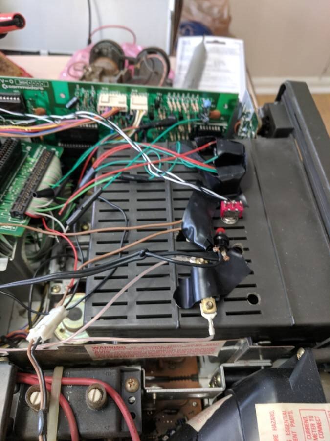
My first Switch Mode Power Supply


I have never messed with a power supply like this before. Mostly a linear supply may have been all that I had dealt with and maybe some AC rectifying, but this was a whole new beast and it was 36 years old too. Finding parts I knew was going to be a hard task as well, if not the equivalents to the original parts I wasn't sure would guarantee that it would work neither.

imageimageimage

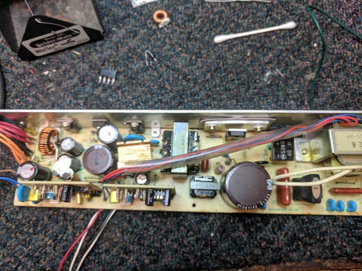
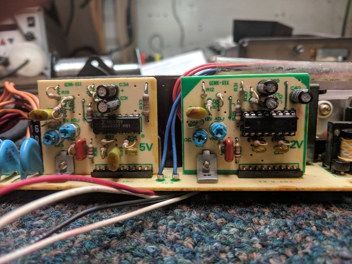
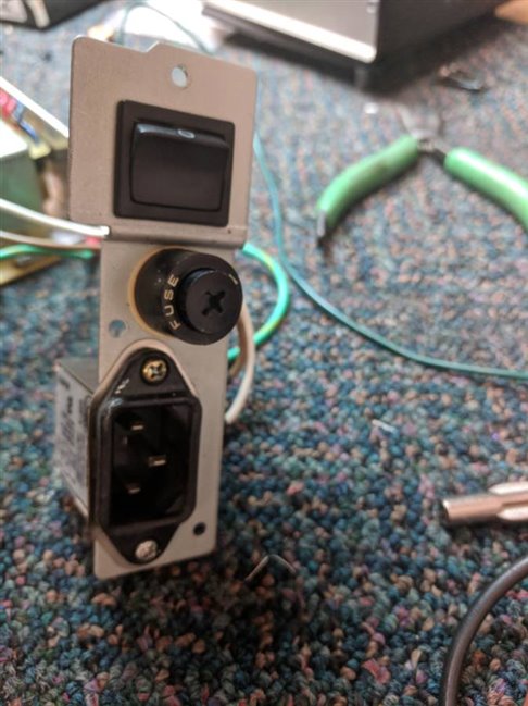
So I am going to fast forward a bit here and just say what was done and what was wrong when it was removed completely from the system. At first it seemed that the 12 volts was still being supplied but after a time that even quit. It was observed that the fuse kept blowing and that was because the one power transistor after the full bridge rectifier would short out and take out the PWM IC on the 12 voltage board as well! Those have been the three components that have been replaced consistently with no real answer as to how come. All electrolytic capacitors and mica one have been checked with an ESR meter to test for resistance, and everything comes back fine. I have tested that actual resistors and diodes and still no shorts or erratic resists readings at all!


If you are wondering what about the 5 volts in all this, well, there was one inductor that was removed from circuit to isolate the 5 volts from everything else. It was found out that the 5 volts was not producing because of a PNP pass-through transistor, which for the moment we are using a NTE replacement part for testing purposes. There is no load to the supply so this transistor has not shorted out on us at all. The correct ones I do have on hand and did come from element14 lol.


So to this point, about 2/3 of this supply is working. There is still no definitive reason as to how come I keep loosing the fuse, power transistor and PWM IC. With all that has been tested and done one would have thought the problem would have reared its head already, but still everything is not OK just yet. The last thing I suspected but have no proved yet were the cold solder joints of the 12 volt daughter-board seeing one was able to rock it back and forth with no effort at all. I had touched that up and it's solid now to the main circuit board. Everything has been put back into place and ready for another test run, I am just unsure that this will solve the issue or burn up more components.


I was told from the start that troubleshooting a power supply even like this is very tedious and the issue could exist just about anywhere. In the whole of the Commodore community, there is no real documentation or any others out there whom talk or speak about the SX-64 power supply, seeing from what I have found out it just keeps running. I see tons of issues with the power bricks to the breadbox Commodore 64 and tons of solutions that way, but none to the effect of solving a switch mode supply and how come it would fail.


imageimage  

If anyone has any further suggestions or happens to be an expert in this field, I appreciate any feedback at all. The only thing left on my mind is that this may be a lost cause and the supply is beyond saving already.

  • Sign in to reply

Top Comments

  • mcb1
    mcb1 over 7 years ago +3
    A trick taught to me for fixing switchmode supplies .... Feed the mains through a 100/150w mains lamp to the device. If there is a fault, it will light the lamp, and usually not damage the surrounding…
  • genebren
    genebren over 7 years ago +2
    It would seem that finding a replacement power supply would be far easier, but maybe not a satisfying than fixing the original. Find a donor system with a working power supply, or just replace the supply…
  • ajkatz83
    ajkatz83 over 7 years ago in reply to genebren +2
    No doubt. Some of the systems I loved as well are emulated nowadays, it does make it all more easier and portable that way. I suppose I do have a back up plan with a Meanwell supply I have an a little…
  • mcb1
    mcb1 over 7 years ago in reply to ajkatz83

    Possibly this got lost.


    A trick taught to me for fixing switchmode supplies ....

    Feed the mains through a 100/150w mains lamp to the device.

    The idea is that any issues or loading will start illuminating the lamp.

    This could be better than a 2A fuse which is likely to start allowing more power to the bit that's faulty.

    Last thing you want is to let out lots of the magic smoke.


    Mark

    • Cancel
    • Vote Up 0 Vote Down
    • Sign in to reply
    • More
    • Cancel
  • ajkatz83
    ajkatz83 over 7 years ago in reply to mcb1

    There is a whole retro computer culture out there definitely. I have found a lot of this at the local gaming conventions that I go to and if you're looking for it there is usually someone with vintage Mac and the Commodores all doing there demos. The best hardware I have seen and have for it is 64NIC and basically it's ether net and can be bridged for WiFi. There is a terminal program for it but haven't had any luck there.


    That's true, I had found some lamps from my class parts project, long past, and have both soldered together and ready to be used as a 12 volt load. Also, we used a pico fuse, too, that is in line with the rectified AC though sadly at a 0.5 amp the fuse blew instantly though didn't take any of those components down at all. Going to try a 2A pico fuse and see if that holds at all. Traditionally on the schematic. pico fuse is in place of R1 some kind of MOV possibly and must be holding off some intense current.

    • Cancel
    • Vote Up 0 Vote Down
    • Sign in to reply
    • More
    • Cancel
  • mcb1
    mcb1 over 7 years ago

    Just another thought.

    A lot of earlier supplies had 'crowbar' devices that would detect some abnormal condition and trip the fuse, etc.


    Modern supplies tend to have better control IC's and can handle these events properly.


    There are also a few capacitors to the frame ground.

    It's possible that one of these could be faulty.


    Mark

    • Cancel
    • Vote Up +1 Vote Down
    • Sign in to reply
    • More
    • Cancel
  • mcb1
    mcb1 over 7 years ago

    A trick taught to me for fixing switchmode supplies ....

    Feed the mains through a 100/150w mains lamp to the device.

    If there is a fault, it will light the lamp, and usually not damage the surrounding components ... ie those explosions of sparks you see in the movies. image


    Generally switchmode supplies will run happily without load, but some seem to rely on the load and it's filtering to smooth the voltage.


    Nice to see these coming back to life.

    My mother purchased one new way back, and then kept it.

    My son now has it and it still works ... well last time he fired it up.


    Mark

    • Cancel
    • Vote Up +3 Vote Down
    • Sign in to reply
    • More
    • Cancel
  • ajkatz83
    ajkatz83 over 7 years ago in reply to dougw

    It is interesting you have said that, we have been running this with no load. According to another person I consulted, I understand that the switch mode type here need to have a load of some kind. That was the last piece of advice I was given and forgot to mention here. I don't know if that'll make a difference or not.

    • Cancel
    • Vote Up +1 Vote Down
    • Sign in to reply
    • More
    • Cancel
>
element14 Community

element14 is the first online community specifically for engineers. Connect with your peers and get expert answers to your questions.

  • Members
  • Learn
  • Technologies
  • Challenges & Projects
  • Products
  • Store
  • About Us
  • Feedback & Support
  • FAQs
  • Terms of Use
  • Privacy Policy
  • Legal and Copyright Notices
  • Sitemap
  • Cookies

An Avnet Company © 2025 Premier Farnell Limited. All Rights Reserved.

Premier Farnell Ltd, registered in England and Wales (no 00876412), registered office: Farnell House, Forge Lane, Leeds LS12 2NE.

ICP 备案号 10220084.

Follow element14

  • X
  • Facebook
  • linkedin
  • YouTube