


I just started on a project to familiarise myself with the TCN75-3.3MOATCN75-3.3MOA Temp sensor from Microchip.
I have used a PIC24FJ64GA004 microcontroller, mainly to practice programming the PIC24F.
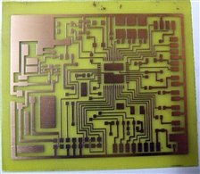
Below is a pic of the etched PCB board ready to be drilled, tinned, and all components soldered.
I will write a detailed report on the project and make the files available as time allows.
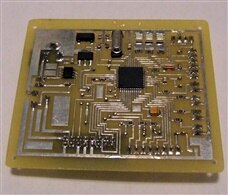
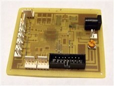
Board Etched Tinned, Drilled, and Populated Ready for Testing
Design & Build notes:
The TCN75-3.3V Temp sensor control board is a good example of HOW NOT TO design a circuit. I short cut my usual rigorous design process to allow me to quickly get started on learning how to program the PIC24 microcontroller.
I decided what I wanted the circuit to do:
Program (in C) a PIC24F microcontroller to communicate via I2C bus with a TCN75-3.3V temperature sensor. (The PIC24F has known problems in Master I2C mode)
and:
Output data via serial to PC using USB to serial cable (No USB OTG on PIC24F)
Display Data on 16*2 Character LCD to user.
Status LED's and User Input (Switch/Button) for added functionality later.
I decided on a whim to use 3 status LED's and had room for 4 inputs for switches/buttons.
The reason behind these decisions:
I wanted to learn how to develop code in C for the I2C comms, Micro to PC serial link, and displaying data on an LCD. All of which I have done before, although not in C as I have mainly used assembler in the past. I have never used the PIC24 series before either.
I also wanted to practice with NI Labview and see if I could get data into Labview from the serial link.
All of which will be used in future projects that I wish to complete.
