


So the printer is built and all of the carriages move nice and smoothly. Now there is a wad of wires, switches and electrical parts that need to be all connected in order to make this printer, print. If you remember at the tail end of Part 1, I gave a link to a YouTube video which, at the beginning of the video, it showed a few tools and supplies to get. I would recommend purchasing these supplies and getting a hold of these tools. It will make the electrical portion go a bit easier. Place the ferrules on the ends of the all of the wires that connect to the terminal blocks on the circuit board and crimp them. I found that trying to twist the wires and place them into the blocks did not work. The wires came out every time the printer was bumped or touched. I did order a mosfet for the heat bed, but after using the ferrules I may just leave things the way they are. I would suggest installing the wires into the circuit board while the circuit board is not mounted on the printer. I mounted the circuit board on the acrylic mount parts, using required mounting screws and steppers, then attached the electrical wires.
There are only 6 wires that need to be placed into the terminal blocks. Once all of the wires are secured, you can mount the circuit board onto the railing on the printer.

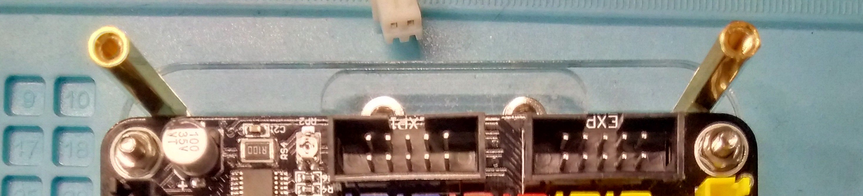
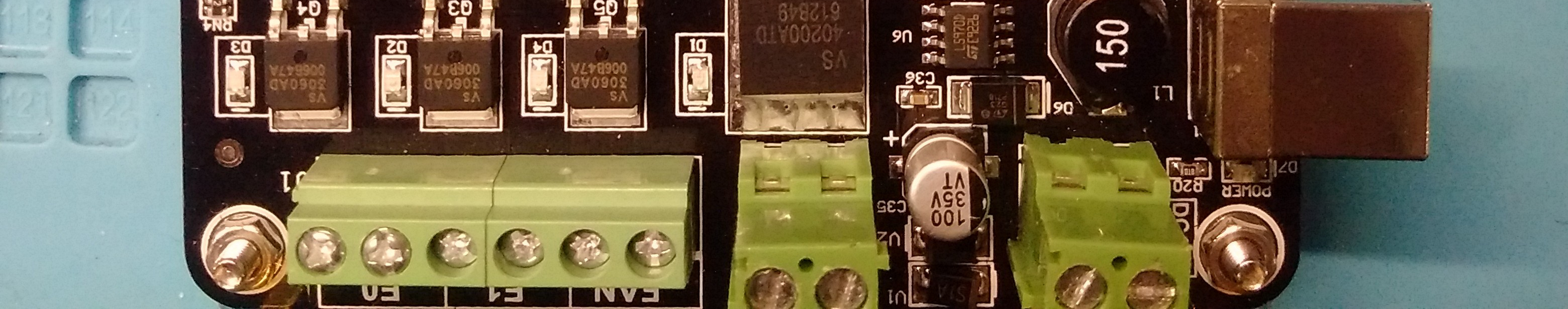
In the above image, left to right are the following:
- Nozzle, thin red wires and it does not matter which side of the block they go in.
- Heat-bed, polar requirements, negative on the left, positive on the right.
- Main power, polar requirements again, positive on the left and negative on the right.

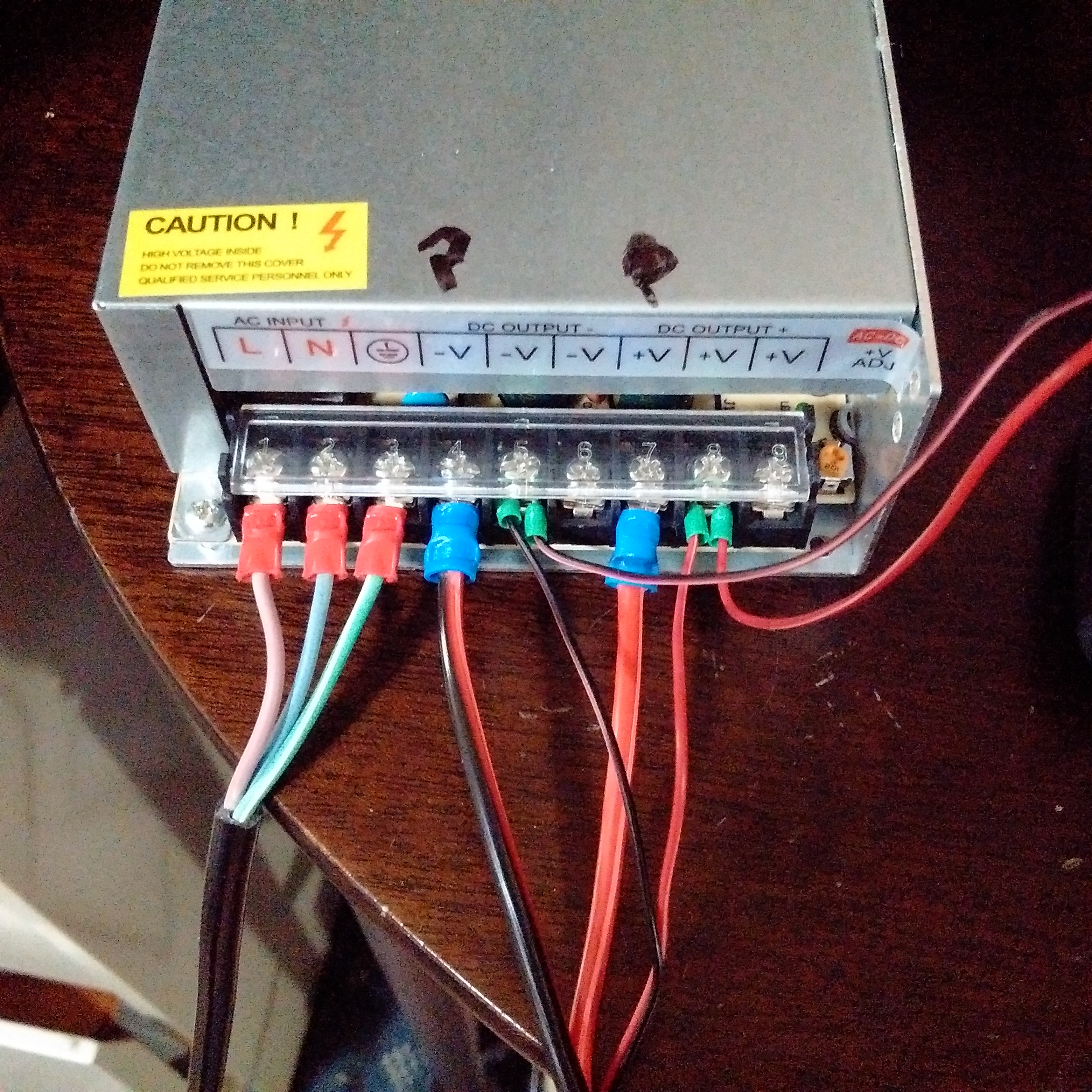
Mount the board to the printer and secure with the M4 and "T" nuts. I have read people have installed the circuit board with the electrical wires on the top. Reason being, the wires were less likely to come out. Your decision. Once this done, the rest of the wiring is a snap, literally. In the back of manual, there is a schematic drawing for the wires. I followed the drawing and plugged in all of the wires to the board. Next attach the wires to the main power supply. I would recommend using wire connectors and a crimper to place ends on these wires as well.
Once the cables and wires are plugged into the circuit board, including the two ribbon cables that go to the LCD, you can place the cover onto top of the circuit board. Now plug the power cable into the wall and see if things power up.


In the image in the above right, the fan and mounting pate that covers the circuit board is laying on the power supply. I've tucked the cables and wires back onto the board and placed only 2 screws to hold the cover on top of the circuit board. I want to try and find a way to clean up the wires and cables. For now it is working. I have placed a couple of the wires from the rear of the unit, into the railing of the frame and then covered the slot with one of the 3 long, thin, plastic and"U" shaped parts that are located on the bottom layer of the box, Layer "C". There is the heavy coil, black housing that one can stuff cable into and I did use part of it to hold the wires from the heat-bed. I have seen lots of wire/cable tie ups on Thingiverse that you can print once your ready to go.
At the end you will have a limit switch and a heat sensor left over. These are both spares and there should be some of the small bags with screws, washers, spacers and nuts. These too are spares.
All in all the electrical part of the printer set up did not go too badly. The biggest problem I had was keeping the power and the heat-bed wires connected to the circuit board. After that, I had a small glitch in the which motor was connect to which port on the circuit board. Not sure why I could not get thru my head which was the "X" and which was the "Z" stepper motors. Once it was pointed out the motors may be connected to the wrong connector on the circuit board, the "Home All" command on the LCD worked as it is suppose to. So, take your time and make sure the connectors and wires are in the correct ports.
The Limit Switches are the next thing to focus on. The "Y" axis (heat-bed) has one of these switches and if you mounted as per the installation video, it should be just fine where it is. Mine was just fine. The "X" axis (slides back and forth) has the switch mounted on the carriage and I never had to adjust anything there either. The "Z" axis (goes up and down) has a limit switch mounted on a bracket on the back of the frame, near the bottom. Kind of behind the circuit board. This bracket/switch will need to be adjusted and it may take a few cracks at it. This ties into the bed ("Y") leveling. Once you get the bed leveled and the nozzle just right, lock the bracket in place.
I'm sure there is a lot I've missed in this part, but if you're stuck, head on over to the Tevo Facebook Page. Lots of very knowledgeable people that can help out.
In Part 3, I'm going to attempt to showing off the LCD and heading towards your first print.
Top Comments