element14 Community
element14 Community
    Register Log In
  • Site
  • Search
  • Log In Register
  • Members
    Members
    • Benefits of Membership
    • Achievement Levels
    • Members Area
    • Personal Blogs
    • Feedback and Support
    • What's New on element14
  • Learn
    Learn
    • Learning Center
    • eBooks
    • STEM Academy
    • Webinars, Training and Events
    • Learning Groups
  • Technologies
    Technologies
    • 3D Printing
    • Experts & Guidance
    • FPGA
    • Industrial Automation
    • Internet of Things
    • Power & Energy
    • Sensors
    • Technology Groups
  • Challenges & Projects
    Challenges & Projects
    • Design Challenges
    • element14 presents
    • Project14
    • Arduino Projects
    • Raspberry Pi Projects
    • Project Groups
  • Products
    Products
    • Arduino
    • Dev Tools
    • Manufacturers
    • Raspberry Pi
    • RoadTests & Reviews
    • Avnet Boards Community
    • Product Groups
  • Store
    Store
    • Visit Your Store
    • 'Choose another store...'
      • Europe
      •  Austria (German)
      •  Belgium (Dutch, French)
      •  Bulgaria (Bulgarian)
      •  Czech Republic (Czech)
      •  Denmark (Danish)
      •  Estonia (Estonian)
      •  Finland (Finnish)
      •  France (French)
      •  Germany (German)
      •  Hungary (Hungarian)
      •  Ireland
      •  Israel
      •  Italy (Italian)
      •  Latvia (Latvian)
      •  
      •  Lithuania (Lithuanian)
      •  Netherlands (Dutch)
      •  Norway (Norwegian)
      •  Poland (Polish)
      •  Portugal (Portuguese)
      •  Romania (Romanian)
      •  Russia (Russian)
      •  Slovakia (Slovak)
      •  Slovenia (Slovenian)
      •  Spain (Spanish)
      •  Sweden (Swedish)
      •  Switzerland(German, French)
      •  Turkey (Turkish)
      •  United Kingdom
      • Asia Pacific
      •  Australia
      •  China
      •  Hong Kong
      •  India
      •  Korea (Korean)
      •  Malaysia
      •  New Zealand
      •  Philippines
      •  Singapore
      •  Taiwan
      •  Thailand (Thai)
      • Americas
      •  Brazil (Portuguese)
      •  Canada
      •  Mexico (Spanish)
      •  United States
      Can't find the country/region you're looking for? Visit our export site or find a local distributor.
  • Translate
  • Profile
Personal Blogs
  • Members
  • More
Personal Blogs
Legacy Personal Blogs The Voltage Divider
  • Blog
  • Documents
  • Mentions
  • Sub-Groups
  • Tags
  • More
  • Cancel
  • New
Blog Post Actions
  • Subscribe by email
  • More
  • Cancel
  • Share
  • Subscribe by email
  • More
  • Cancel
Group Actions
  • Group RSS
  • More
  • Cancel
Engagement
  • Author Author: SGarciaV
  • Date Created: 27 Nov 2015 12:41 AM Date Created
  • Views 680 views
  • Likes 3 likes
  • Comments 10 comments
  • msp340fr6989
  • voltage
  • launchpad
  • divider
Related
Recommended

The Voltage Divider

SGarciaV
SGarciaV
27 Nov 2015

Introduction


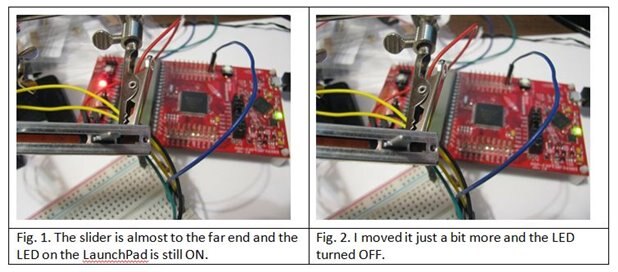
I just finished a course programming the TI LaunchPad, featuring the MSP340FR6989 micro controller. One of the lab projects involved a sliding potentiometer which turned a LED “on” or “off” depending on how far the arm on the pot was to either end.


The software for this lab that was provided by the course polled the Analog to Digital Converter (ADC) to determine whether the input voltage to the ADC was at 50% of the full potential. If it was above the 50% mark the LED turned “on”. Otherwise the LED turned “off”.


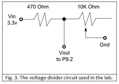
The LaunchPad uses 3.3v; therefore, the voltage at 50% would be 1.65v. I noticed that I needed to move the pot’s arm almost to one end for the LED to turn “off”. I would have expected the switching to happen somewhere around the midpoint of the pot’s slider. I decided to have a closer look to determine what was going on.

image


The Voltage Divider


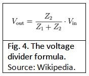
The circuit used in the ADC lab is a simple voltage divider. This type of circuit is used to quickly and simply take an input voltage and reduce it to a certain level. While this type of circuit is not appropriate for every situation, it is practical since it requires only two resistors. The schematic for how the lab’s pot was wired to the LaunchPad is shown in Figure 3.

image

The input voltage (Vin) is 3.3v and is sourced directly from the LaunchPad. As mentioned earlier, a voltage divider consists of two resistors. In this case, the first resistor is 470 Ohms and is connected to Vin. The second resistor is connected in series with the first and is a 10K variable resistor, or potentiometer. The other end of the slider pot is connected to ground. The Vout voltage going to the LaunchPad’s P9.2 pin is tapped from between the two resistors. Vout depends on both of these resistors’ values.

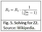
How can we know what Vout will be depending on the resistor values?  Luckily for us, there is formula for that, as shown in Figure 4 which I borrowed from Wikipedia.

image

Z1 and Z2 are the two resistors. Using this formula we can calculate the theoretical Vout by filling in the values for Vin and the two resistors. We know that Vin is 3.3V and we’ll assign Z1 to the 470 Ohm resistor. Our slider pot is Z2. We can vary the resistance of this component to calculate Vout. In fact, we’ll go a step more. Since the software is supposed to switch the LED when it reaches 50% of Vin, we also know Vout: 1.65v. Now we can solve for Z2 and see what the resistance of the pot should be for the LED to switch. Luckily, Wikipedia also provides the formula to solve for either resistor. Since we arbitrarily assigned Z1 to the 470 Ohm resistor and the 10k slider pot to Z2, we want to solve for Z2 as is shown in Figure 5.

image

Let’s analyze this formula for a moment. The key is in the division in the denominator. We want Vout to be half of what Vin is, so of 3.3v we want 1.65v. What do we get when we divide a number by half of itself? We always get 2! Then if we subtract one from that we always get 1 and it doesn’t take a trig expert to know that 1 / 1 is 1. The conclusion is that in the specific case when we want Vout to be half of Vin, the second term cancels out because it will always be one. This just leaves the value of the first resistor. In our case R1 (or Z1, depending on which formula you are looking at) is 470 Ohms; therefore, to get 1.65v out of 3.3v the pot resistance needs to be 470 Ohms. The following table shows the first formula in action based on varying values of the slider pot.


image


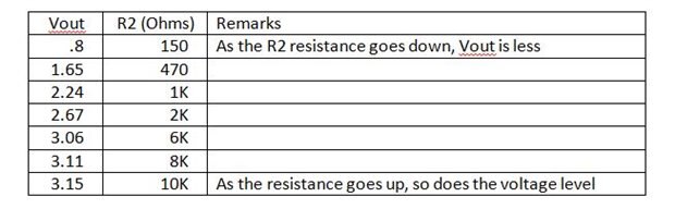
While we could tend to think that the LED will switch “on” and “off” when the slider is halfway because the software is checking for half the input voltage, this is only an illusion. Having the LED switch when the slider is almost at the end of the slider makes sense because the slider needs to be where the pot’s resistance is 470 Ohms and if the pot’s total resistance is 10K (as in 10,000) then 470 Ohms is expected to be almost at the end that marks 0 Ohms.


What if we wanted the LED to switch when the slider is at the half way mark? Now that we know that both resistances need to be the same value for the voltage out to be half of the input voltage, and we know that the pot’s total resistance is 10K then we can conclude that the halfway point of the pot will give us 5K; therefore the other resistance needs to be 5K. This is as easy as swapping out the 470 Ohm resistance with a 5K resistor (or its closest value).


Regards!


Voltage divider formulas source:

https://en.wikipedia.org/wiki/Voltage_divider

  • Sign in to reply

Top Comments

  • cpa04
    cpa04 over 7 years ago +1
    Nice post, your description is well done! keep in mind@most real applications: https://en.wikipedia.org/wiki/Voltage_divider#Loading_effect
  • cpa04
    cpa04 over 7 years ago

    Nice post, your description is well done!

    keep in mind@most real applications: https://en.wikipedia.org/wiki/Voltage_divider#Loading_effect

    • Cancel
    • Vote Up +1 Vote Down
    • Sign in to reply
    • More
    • Cancel
  • SGarciaV
    SGarciaV over 7 years ago in reply to DAB

    Thank you!

    • Cancel
    • Vote Up 0 Vote Down
    • Sign in to reply
    • More
    • Cancel
  • DAB
    DAB over 7 years ago

    Nice post and good description on how to use resistors for voltage adjustment while maintaining protection from shorting the output.


    DAB

    • Cancel
    • Vote Up 0 Vote Down
    • Sign in to reply
    • More
    • Cancel
  • tonyboubady
    tonyboubady over 7 years ago in reply to SGarciaV

    Ok image,  Have a nice weekend too...

    • Cancel
    • Vote Up 0 Vote Down
    • Sign in to reply
    • More
    • Cancel
  • SGarciaV
    SGarciaV over 7 years ago in reply to tonyboubady

    No worries! The FR6989 is a bit heftier, in fact, from what I've read, the LaunchPad does not expose all of its i/o pins. Have a great weekend.

    • Cancel
    • Vote Up 0 Vote Down
    • Sign in to reply
    • More
    • Cancel
>
element14 Community

element14 is the first online community specifically for engineers. Connect with your peers and get expert answers to your questions.

  • Members
  • Learn
  • Technologies
  • Challenges & Projects
  • Products
  • Store
  • About Us
  • Feedback & Support
  • FAQs
  • Terms of Use
  • Privacy Policy
  • Legal and Copyright Notices
  • Sitemap
  • Cookies

An Avnet Company © 2023 Premier Farnell Limited. All Rights Reserved.

Premier Farnell Ltd, registered in England and Wales (no 00876412), registered office: Farnell House, Forge Lane, Leeds LS12 2NE.

ICP 备案号 10220084.

Follow element14

  • X
  • Facebook
  • linkedin
  • YouTube