

Spectrum analyzer |
|---|
A spectrum analyzer measures the magnitude of an input signal versus frequency within the full frequency range of the instrument. The primary use is to measure the power of the spectrum of known and unknown signals. The input signal that a spectrum analyzer measures is electrical, however, spectral compositions of other signals, such as acoustic pressure waves and optical light waves, can be considered through the use of an appropriate transducer. Optical spectrum analyzers also exist, which use direct optical techniques such as amonochromator to make measurements. By analyzing the spectra of electrical signals, dominant frequency, power, distortion, harmonics, bandwidth, and other spectralcomponents of a signal can be observed that are not easily detectable in time domain waveforms. These parameters are useful in the characterization of electronic devices, such as wireless transmitters. The display of a spectrum analyzer has frequency on the horizontal axis and the amplitude displayed on the vertical axis. To the casual observer, a spectrum analyzer looks like an oscilloscope and, in fact, some lab instruments can function either as an oscilloscope or a spectrum analyzer. (Wikipedia) |
| MCU Hercules RM57 (Texas Instruments http://www.ti.com/lit/ds/symlink/rm57l843.pdf) | ||
|---|---|---|
The RM57L843 device is a high-performance microcontroller family for safety systems.
The device has Built-In Self Test (BIST) logic for the CPU, the N2HET coprocessors, and for on-chip SRAMs. The device supports ECC protection on the L1 caches, L2 flash, and SRAM memories. The device also supports ECC or parity protection on peripheral memories and loopback capability on peripheral I/Os.
The RM57L843 device integrates two ARM Cortex-R5F floating-point CPUs, operating in lockstep, which offer an efficient 1.66 DMIPS/MHz, and can run up to 330 MHz providing up to 547 DMIPS. The device supports the little-endian [LE] format. The RM57L843 device has 4MB of integrated flash and 512KB of data RAM with single-bit error correction and double-bit error detection. The flash memory on this device is a nonvolatile, electrically erasable and programmable memory, implemented with a 64-bit-wide data bus interface. The flash operates on a 3.3-V supply input (the same level as the I/O supply) for all read, program, and erase operations.
The SRAM supports read and write accesses in byte, halfword, and word modes. The RM57L843 device features peripherals for real-time control-based applications, including two Next Generation High-End Timer (N2HET) timing coprocessors with up to 64 total I/O terminals.
The N2HET is an advanced intelligent timer that provides sophisticated timing functions for real-time applications. The timer is software-controlled, with a specialized timer micromachine and an attached I/O port. The N2HET can be used for pulse-width-modulated outputs, capture or compare inputs, or GPIO. The N2HET is especially well suited for applications requiring multiple sensor information or drive actuators with complex and accurate time pulses. The High-End Timer Transfer Unit (HTU) can perform DMA-type transactions to transfer N2HET data to or from main memory. A Memory Protection Unit (MPU) is built into the HTU. |

| Operation Design |
|---|
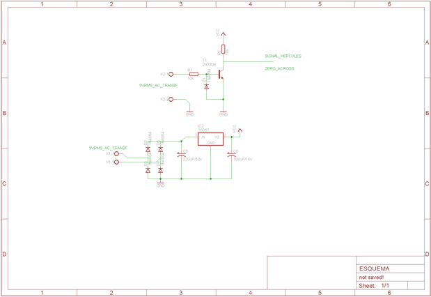
In this small project, design a frequency meter high accuracy parser should I use a timer with a definition of microseconds, the Hercules RM57 has internal modules for measurement of time with high precision, in my application I use a common transformer that reduces the voltage, our goal is to measure the frequency is accurate.
The frequency is the same throughout the country (Peru), so in factories that use high power motors must have the same error rate that we introduce at home.
The line frequency variations are bad, because they reduce the lifetime of high-power engines, these variations produce that warm the engine and vibrate reducing their lifetime, one solution would help monitor the frequency of feeding the engines not work with speed and provide preventative maintenance.
|
Schematic and BoosterPack

| Main program |
|---|
for (ii = 0; ii < Samples; ii++) { //samples =2**N N128,256,1024,512
capturaadc();
imaginaryNumbers[ii] = 0; // imaginaryNumbers_1[ii] = 0;
// realNumbers_1[ii] = adc_data[0].value - adc_data[2].value; // Corriente realNumbers[ii] = adc_data[1].value - adc_data[2].value; // Voltaje
wait_secons(2 * 980e-6); // tiempo de muestreo
}
gst_spectrum_window(realNumbers, Samples); /*gst_spectrum_window--> se aplica una ventana de Hanning a la entrada (tiempo)*/ gst_spectrum_fix_fft(realNumbers, imaginaryNumbers, 9, 0); /*realiza la FFT o FFT inversa*/ gst_spectrum_fix_loud(loud, realNumbers, imaginaryNumbers, Samples / 2, 0); /*gst_spectrum_fix_loud--> calcula el volumen de la señal, para cada punto de frec. El resultado es una vector de enteros, las unidades son dB (valores deben ser negativos)*/
for (ii = 0; ii < Samples; ii++) { spect[ii] = (int) loud[ii]; spect[ii] = (int) loud[ii] + 17 + 65;// agrego 17dB, para eliminar el offset de 3.3v en dB if (spect[ii] < 0) spect[ii] = 0; }
capGetSignal(hetRAM1, cap6, &signal_datos);
float64 frec_line = (float64) 1 / (signal_datos.period * 1e-6);
float Error = (60 - frec_line) / 60; Error = fabsf(Error * 100); float error_ppm=Error*10000; /*1% = 10000ppm Tolerancia: ppm significa una incertidumbre de un millonésimo de la medición.*/
sprintf(Mensaje, "%f Hz", frec_line); sprintf(Mensaje2, "%4.2f ppm ", error_ppm);
glcd_fillScreen(OFF); glcd_rect(0,0,127,20, 0, 1);
glcd_rect(0,20,127,63, 0, 1);
glcd_text57(10, 2, Mensaje, 1, 1); glcd_text57(10, 12, Mensaje2, 1, 1);
glcd_text57(100,25,"FFT", 1, 1);
int x, ymax = 63, a = 0; for (x = 1; x < 128; x++) { glcd_rect(a, ymax - spect[x], a, 63, 1, 1); a++; } glcd_update();
// gst_spectrum_window (re, spec_len); // gst_spectrum_fix_fft (re, im, spec_base, FALSE); // gst_spectrum_fix_loud (loud, re, im, spec_len, 0); /* step = spec_len / (spectrum->width * 2);
for (i = 0, pos = 0; i < spectrum->width; i++, pos += step) { if (loud[pos] > -60) spect[i] = (loud[pos] + 60) / 2; else spect[i] = 0; /* if (spect[i] > 15); */ /* spect[i] = 15; */ //} |
Links: |
|---|
Hercules Main Program Download click here
related project: TI Hercules LaunchPad Tipo 2: Electromyography Signal DSP part 2 The specified item was not found. |