

| GOAL |
|---|
| My goal is to design a power quality analyzer with which voltage, current, active power, reactive power, apparent power, line frequency, power factor, crest factor and power disturbances is determined. |
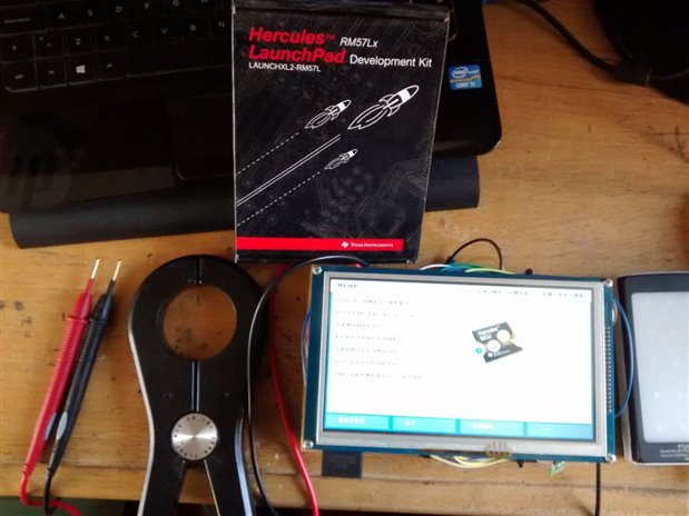
| TI HERCULES RM57Lx as main processor |
|---|
 |
| EQUIPMENT SPECIFICATIONS |
|---|
FEATURES EQUIPMENT
• Measures up to 600 Rms • Measures up to 100 Arms • Displays the current maximum values, average, crest factor and voltage • Calculates and displays apparent power, active power, reactive power and power factor. • Measure and record power parameters KW, KVAR, VA • Displays the total harmonic distortion THD of voltage, current and power, • Displays individual harmonic values up to the value 59. • Records, captures and displays current and voltage fluctuations. • Storage FAT format, up to 100GB. • Max and Min rms values are calculated by period.
EQUIPMENT SPECIFICATIONS
RMS voltage: 600V phase to neutral Current: 100A System: Single phase Frequency: 50-60Hz. Measurements of power: kW, kVAR. Energy measurements: kWh, kVARh, kVAh. Measuring factors: Power Factor PF, THD Measurement and transient recording: Voltage and Current Measurement of Harmonics: Up # 59, direction and sequence Measure and record: THD harmonic distortion. Sampling Frequency: 460 measurements per cycle. Storage Capacity: 4GB Power Supply: AC 220Vrms / Battery. Battery operation: - Communication: Bluetooth Display: TFT LCD Touch
SPECIFICATIONS ELETRICAS PROTECTION
• Input voltage: 220Vac +/- 10% • System: Single phase • Input frequency: 50-60Hz • Overcurrent: Fuse • transient protection: Varistor 130 Joules
SPECIFICATIONS MEASUREMENT SYSTEM AND PROCESSING
• Processor: ARM CORTEX-R5F / TEXAS INSTRUMENTS • Number of Bits: 32 & 16 bit • Processor Speed: 547MIPS / 330MHz • ADC converter: 12 bits / 3.3 v
SPECIFICATIONS Display Module
• The module user interface is an LCD touch screen used for: Configurations or navigation between programs or Display parameters or Display Alarms
• Display: color LCD screen 7-inch • Resolution: 800 x RGB x 480 Pixel • Input: Touch Panel.
COMMUNICATION SYSTEM
• Interface: Wireless • Output Format: ASCII 8N1 (8 bits, no parity, 1 stop bit) • Transmission speed: 9600 • Wireless Communication: Bluetooth. |
| VIEW OF MEASURING INSTRUMENTS |
|---|
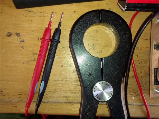 |
| Voltage Probes | CLAMP FLUKE 80i -600 A |
|---|---|
 |  |
| Voltage Probes | |
|---|---|
 | probes are connected to line 220 Vrms/60Hz (Peru).
Probes have insulation up to 1000 Volt CAT II.
the equipment is designed to measure a voltage of 600Vrms Maximo and for this reason the level of protection is quite acceptable for PQA |
| CLAMP FLUKE 80i -600 A | ||
|---|---|---|
 | The 80I-400 is compatible with any multimeter capable of reading ac current equal to 1/1000 of the current to be measured, and equipped with input jacks compatible with Fluke safety-designed test lead connectors.
need only embrace a conductor to be measured. |  |
Note: my native language is Spanish and equipment instructions must necessarily are in my language, hope your understanding.
| Task List the Power Quality Analyzer team can do |
|---|
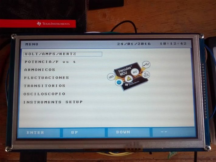 |
| OVERVIEW OF TASKS |
|---|
the whole program was developed on the launch pad Hercules RM57 company Texas Instruments, also Cortex-R DSP Software Library applied for the analizis of analog signals.
1. Capture the analog signals by the ADC / 12-bit resolution. 2. Control of TFT LCD screen, the NHEt module. 3. Measure the voltage period as frecuency by NHEt module. 4. Control Clock, Chip Touch, SD and EEPROM memories, for the MIBSPI module. 5. Peripherals extras controlled by the GIO module.
The microcontroller has a high capacity and flexibility that allowed me to make the following algorithms: |
| VOLTAGE, AMP AND FREQUENCY | |
|---|---|
 | In this mode, can perform tasks such as zoom in and out the size of the waveform, enable or disable the digital trigger, you can also alter the sampling time. |
 | This task allows to display the waveform of voltage and current in a single screen, on the same can see the measurement of RMS voltage and RMS current, and also capturing the HERZ with two decimal precision. |
| ELECTRIC POWER AND GRAPHICS (HZ vs Time) | |
|---|---|
 | Within the stage of this program we can find the measurement by cycle RMS voltage and AMP.
after to obtain the values of voltage and current, calculate the apparent power.
the fast Fourier transform is applied to the voltage and current signals to obtain the phase of the fundamental in both and to calculate the phase angle between the two signals.
with the angle of lag it is possible to calculate the remaining power:
- Reactive power. - Real power. |
 | on the right side of the image shows an XY graph line frequency versus time, each space between points means 5 seconds.
The graph has limits in my case, the limit is between 61Hz and 59 Hz, with 10 divisions between the central value 60Hz and upper and lower ends. |
 | this image shows the variation of the measured frequency. |
| Harmonic Analysis | using FFT harmonics of the power line is analyzed, the maximum is harmonious # 59 |
|---|---|
Harmonic voltage signal | Harmonic voltage signal with Harmonic #5 highlighted by the cursor |
Harmonic amp signal | Harmonic amp signal with Harmonic #5 highlighted by the cursor |
Harmonic power signal | in the upper left part of the images you can see the data captured by the cursor on the screen (still in development).
for the electrical frequency spectrum, it was necessary to use a frequency convolution, between the spectra of voltage and electric current. |


| FLUCTUATIONS |
|
|---|---|
records the voltage and current cycles, stored in its memory the RMS value for a second sample to then calculate the maximum and minimum voltage and current during that period.
while it is generating an XY graph in the TFT LCD screen, where you can observe the variation of voltage and current in time.
| At the end of the program, it stored in the SD memory one excel file with all the recorded measurements. |


| TRANSIENT DETECTOR / VOLTAGE | |
|---|---|
 | A sample of three periods of alternating signal is taken, then a pure sinusoidal signal, which acts as an envelope is applied.
if there is a transient in the signal switches registered, this is detected and the event is stored in the memory of the MCU.
PQA has memory for 20 transient events. |
| TRANSIENT captured and logged | |
|---|---|
 |  |
 |  |
 |  |
 | - A cursor in which we can navigate between XY graphs is implemented.
- The cursor shows the measurement of the instantaneous voltage and the time the event occurred.
- At the bottom you can see the maximum and minimum voltage. |
| Scope Mode / LOW BANDWIDTH |
|---|
The oscilloscope task, allow me to use the basic functions of an oscilloscope, zoom in and out the graph, play time, the graph move up and down, turn on or off the trigger. |

| BLUETOOTH MODE (still developing) |
|---|
 |
| Version of the system and sensitivity calibration of the electrical clamp |
|---|
 |
| PICS |
|---|
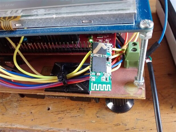
BLUETOOTH MODULE
|
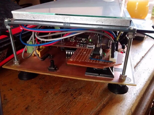
| Images of development BOOSTERPACK |
|---|
Hercules RM57 and BOOSTERPACK |


| Videos (spanish) |
|---|
PART I PART II PART III PART IV
|
Author's comments:
I would like to give many details about the project, but it is not possible for the reason that this project is my thesis for a degree in electrical engineering.
for the month of May 2016, I will share the program and schematic here on element14.
Comentarios del autor:
Me gustaría dar muchos mas detalles sobre el proyecto, pero no me es posible por el motivo de que este proyecto es mi tesis para obtener el titulo de Ingeniero Electrónico.
para el mes de mayo del 2016, yo compartiré el programa y los esquemáticos aquí en Element14.
Top Comments