


Way back in 2007, when a lot of us were enthralled by immersive 3D worlds like SecondLife, I had a great idea for a novel type of clock, which I called the "TimeFrame".
I wasn't sure if the idea would be quite as cool in reality as it was in my head, and I knew that making a physical version of this device would be mechanically difficult, time consuming, and expensive.
So I decided to build a prototype TimeFrame in the SecondLife 3D immersive world, which was a LOT easier than building it in real life (or "FirstLife" as we called it!). I could then show a working prototype to other people in SecondLife to see if they thought it was as cool as I did.
Here's a blog post plus video I wrote about the virtual TimeFrame in July 2007. I was completely convinced that the TimeFrame *was* as cool as I suspected it would be, and from then on, have harboured a desire to build a real TimeFrame.
So what is the TimeFrame? It's a continuously updating binary display of a number called the Unix Datestamp that computers all over the world use to count the number of seconds since a notional "beginning of time" on 1st January 1970. We're currently up around 1.4 billion (1,436,913,091) seconds. But the TimeFrame displays it in *binary* - 1s and 0s - or, this case, black bars and white bars, which flip over in a mesmerising and rather pleasing way, continuously displaying the current value of the Unix Datestamp that, if you decode it, gives you the date and time to the nearest second.
As an example, a rather visually pleasing date has recently passed in the unix timestamp world: at 2.09AM on 15th May 2015, the unix timestamp was 1,431,655,765. Not very interesting, you may say, until you convert it to binary:
01010101010101010101010101010101
Cool, huh? On the TimeFrame, that would have been alternating black and white slats all the way down the line.
My experience with building the virtual TimeFrame in SecondLife convinced me that the idea *was* as cool as I thought it was, and everyone who saw it thought it was amazing. So I set myself the challenge of one day building a physical TimeFrame, in the real world.
One idea I had was that it would be a garden ornament - one that was big enough to be visible from the aeroplanes that take the photos for Google Earth and other mapping applications, so you would always have a sort of "barcoded" record on the photo of the exact time and date it was taken. That, however, would need the TimeFrame to be about 4 metres long, which seemed like a daunting prospect from a mechanical engineering point of view!
Eight years passed, during which I thought from time to time about how to implement the mechanics of a real-world TimeFrame. I had ideas about using motors, using cams and microswitches to delimit the slat rotation. I thought about stepper motors and geared motors with optical position encoders. All of these, were variously clumsy, complicated, expensive and unreliable, and with 32 slats to automate I needed something much simpler. I eventually settled on servo motors, and hit upon the idea of using slats with right-angle section, so I would only need to turn through 90 degrees rather than 180 degrees to make the transition from black to white.
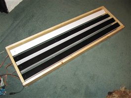
I was still not sure how the mechanical engineering part would go, so, encouraged by Lucy Rogers' projects, I built a 4 digit prototype to validate all the design and construction considerations. Here's an 11 minute video of the prototype and first few next steps:
The slats are made from right-angle section plastic, sold as edging strip. I chose 1m long by 50mm wide slats that were available from a local hardware shop. They are turned using a servo motor which has a 180 degree range. We only need 90 degrees of rotation, so that we can display one side of the slat, or turn through 90 degrees to display the adjacent side.


Using masking tape and spray paint, one side was made black, the other left white.

A small block of wood was screwed to the inside of the slat, and the plastic actuator arm of the servo was screwed onto that. A hole through the middle of the wood block enabled the actuator arm to be screwed onto the rotor of the servo.


The other end of the slat needed a bearing of some sort to allow the slat to rotate under control of the servo motor. A block of wood at that end of the slat had a hole in it and a cocktail stick pushed through. This rested in a hole drilled through the side of the TimeFrame, which was lined with a small length of plastic pipe, to reduce the friction of the bearing.

The holes in the side of the TimeFrame for mounting the servos were very carefully measured, marked and cut out, as I wanted the slats to be as close together as possible, without them hitting each other when they rotated. I used Pythagoras' Theorem to work out the clearance needed by each slat, and ensured that even if two adjacent slats were in the "widest" position at the same time (half way between black and white), they would clear each other with 1mm gap.
The frame of the TimeFrame was made from 18mm x 70mm pine, and was carefully cut to size and the holes for the servos and bearings carefully measured and drilled, as the accurate alignment of the slats required precision in the drilling and cutting.
The servo motors run on 5 Volts, and are controlled from an Arduino micro controller. The Arduino Uno can drive up to 4 servo devices simultaneously, so that was fine for our prototype.

I experimented a lot with the speed of rotation, as I wanted a pleasing "rolling" effect as the digits carried over in the binary sequence. If the servo is turned too slowly, it appears jerky. If too fast it doesn't appear to roll: it just snaps from one position to the other. I also had to make the rolling fast enough that all the slats could be turned, if required, in less than one second. Otherwise, the first digit would need to turn again before the program had finished turning all the slats, so it would fall behind in its time keeping. With just 4 slats this was not a problem, but I realised that a different approach would be needed for the full-size 32 slat time frame, as a long roll of many digits could take several seconds!
A mechanical problem that I discovered, was that servos are sometimes prone to "jitter". The flexibility of the slats meant that when the servo turned them, there was a bit of a twist, and this could over-shoot the required position. In trying to maintain the position they had been set to by the Arduino, the servo would then go back the other way a bit, which would flex the slat the other way, and I sometimes saw quite violent oscillations in the slats as the servo fought to keep them at the desired position.
I tried many ways to solve this problem: making the slat stiffer (with a wooden strip inside), increasing the friction on the far-end bearing (by making a bed of Sugru for the cocktail stick to turn on), replacing the servo, thicker and thinner blocks of wood at the ends of the slats, slower turning, faster turning, different start and end angles for the servo. Eventually, I concluded that the slats were too flexible, and reached a compromise with high friction end bearings and careful selection of the servo angle positions.
In order to set up the correct angles for the black and white position of each slat, I wrote a "tuning" application. In tuning mode, the TimeFrame would start with all slats in what I call "tent" position: half way between black and white. The first slat would then flip into white position, and the knob of a potentiometer could be used to manually turn the servo by telling the Arduino to move the servo one degree at a time in each direction according to the turning of the knob. The angle setting was printed out to the serial port for display on a connected laptop. After the correct angles for the black and white positions of the first slat were identified, a pushbutton was pressed to move on to the next slat. The angle readings are hard-coded into the Arduino application, so that after the tuning process is complete, the TimeFrame in its normal clock mode runs with correct alignment of the slats in their two colour states.
Valuable lessons learned from the prototype:
* Measure twice, cut once!
* Ensure there is enough clearance between the first and last slat and the frame (5mm)
* The length of the slats varies slightly, so ensure there is sufficient clearance at the ends of the slats (5mm at each end)
* Use a thick enough block of wood at the ends of the slats that it doesn't split when the screws are inserted (I used 2.5cm)
* Make sure the frame is high enough that the slats don't hit the ground when they turn. I had to add some wooden blocks to raise it up a bit.
Building the 4-bit prototype gave me the confidence to embark on the much more ambitious, full-size 32-bit TimeFrame. I knew how to overcome all the mechanical, electronic and software challenges that the bigger project would present.
I was able to show the prototype to other people, so they could appreciate the vision that I had for the full-size TimeFrame project.
Bill of Materials for the major electronic components:
Farnell Number | Description | Link |
2112013 | PSU 12V | |
1318719 | Power cord | |
2075382 | Arduino Uno | |
1196440 | Power cord | |
1109888 | PSU 5V | PCM50US05 - XP POWER - ADAPTOR, AC-DC, MEDICAL, 5V, 8A | Farnell element14 |
2075365 | MODULE, MICRO SERVO, TINKERKIT | |
9731156 | HEADER, SQUARE PIN, 2.54MM, 3WAY |

