


In part 1 of this blog, I described the original concept behind the TimeFrame clock, its initial implementation in the SecondLife 3D immersive world, and my 4-bit mechanical prototype.
With the confidence gained from getting the 4-bit prototype working, I embarked on the full-sized 32-bit version.
The biggest design decision for the full-size version, was what size to make the slats. I made a spreadsheet which, for a given slat width, would use Pythagoras to give the maximum operational width of each slat as it turned, and then multiplied up to give the overall dimensions of the resulting TimeFrame clock.
The trouble I'd had in the prototype with the "whiplash" of the slats causing servo jitter, and my desire to have a portable TimeFrame that I could take to conferences and maker fairs, led me to settle on slats that were 60cm long by 32mm wide. This meant the overall size of the TimeFrame would be 150cm long by 64cm wide. The length of the slats was chosen so I could cut 4 from the 2.4m lengths of angle plastic that were available in my local DIY store.
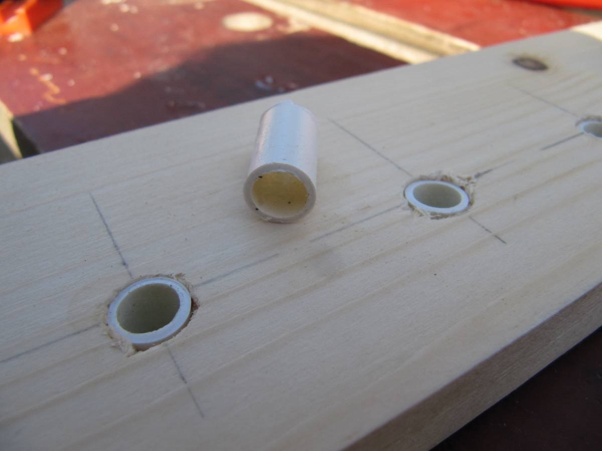
The other design point that needed consideration was the bearings at the far end of the slats. In the prototypes I used a cocktail stick in a hole lined with a length of plastic tubing, to minimise friction. The cocktail sticks were very fragile, so for this version I decided to use the same plastic tube linings, but with a length of 5mm dowel rod.
Having made all the design decisions for the dimensions of the TimeFrame, I was ready to start construction. There were many separate steps or "processes" that had to be carried out, most of which had to be repeated 32 times - once for each slat. I quickly realised two things:
1) 32 times a small number is quite a big number. A process that took just 1 minute to perform would take half an hour to do for the whole set of slats. I realised that this project was going to take many hours of work.
2) being accurate and careful is just as important for the 32nd slat as for the 1st. I had to overcome the temptation to rush things towards the end, when the repetitive nature of the process became tedious.
As an example of some of the process steps and their durations, the first few were:
| mark out servo holes | 60 mins |
| cut servo holes | 120 mins |
| check and trim holes | 60 mins |
| cut far-end holes | 60 mins |
| fit servos | 90 mins |
As you can see, that's more than 6 hours elapsed already!
The major steps were:
| mark and drill the holes in the frame | 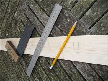 |
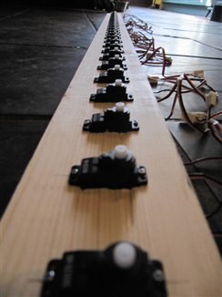
| fit the servos | 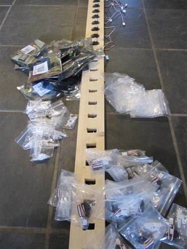 |
| mark, cut and drill the wooden slices for the ends of the slats | 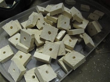 |
| measure, cut, sand, apply masking tape and spray paint the slats (one side black) | 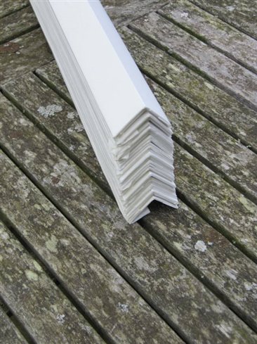 |
| fit wooden slices to slats and attach servo actuator arms | 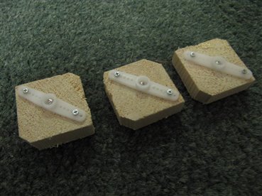 |
| fit slats to servos and insert wooden dowel pegs at other end | 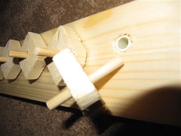 |
| fit floor, sand and stain the frame | 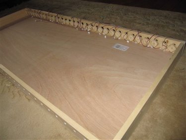 |
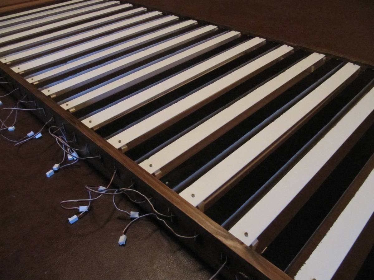
That completed the mechanical construction of the TimeFrame. It was very satisfying to see the result of more than 20 hours work.
However, the clock did not do anything yet, as the servos were not wired up to the controlling computer.
It was interesting to notice that maker projects like this have a number of distinct phases of construction, which require different engineering skills. After the designing and prototyping phases, there are:
mechanical - constructing the actual hardware with the slat actuators and end bearings
electrical - wiring up the servos with power supplies and control signals
electronic - the "tuning" mechanism and the time-keeping system
software - designing, writing and testing the algorithm which would give the aesthetically pleasing "rolling" effect to the slats, and keeping the time and date representation accurate.
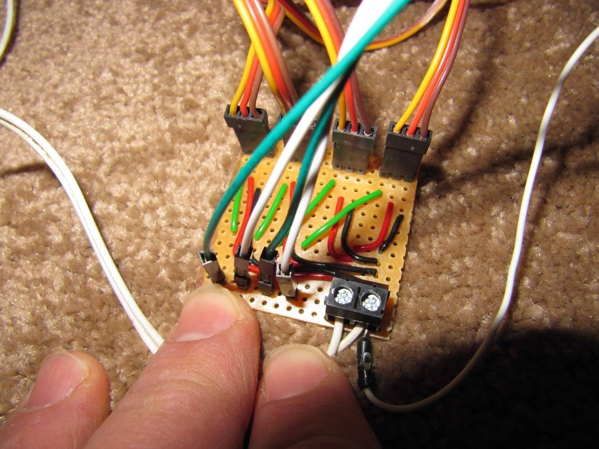
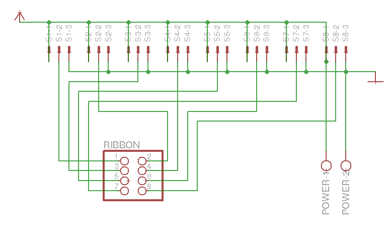
When it came to wiring up the servos, I decided to group the slats into 4 sets of 8. This was mainly because the lengths of the cables on the servos was enough for them to reach 4 slat-widths. So I needed a "multiplexer" circuit board in the middle of each group of 8 slats, with 4 servo cables coming in from each side. I decided to use a ribbon cable to carry the servo control signals from the Arduino controller to the servos. 32 wires at the Arduino end would split into 8 plus 24 at the first multiplexer, another 8 plus 16 at the next, 8 plus 8 at the third, and the final 8 wires would run all the way along to the fourth multiplexer. It reminded me of a Sankey diagram where resources peel off to various destinations.

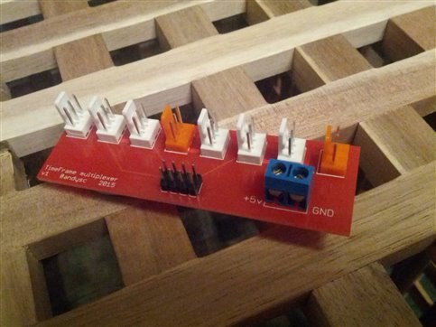
The multiplexer board distributes power from a pair of screw terminals to each of the 8 servos, and links one of 8 pins on the IDC header of the ribbon cable to one of the servo control lines. Not a complicated circuit, but one which would have required a lot of short wires to be soldered onto a solution using Veroboard (my usual preferred circuit-making system).
I decided this would be a good opportunity to venture into the world of designing Printed Circuit Boards. I have been surprised that after nearly 40 years as an electronics hobbyist I have never made a PCB. So it's high time I started!
Inspired and educated by drlucyrogers blog post about making her first PCB, I downloaded the Eagle PCB design software and started working my way through the tutorial. This took quite a long time, but after about a week of snatched moments working on it, I felt competent to tackle my first board.
I first drew the circuit diagram in the Eagle schematic editor.
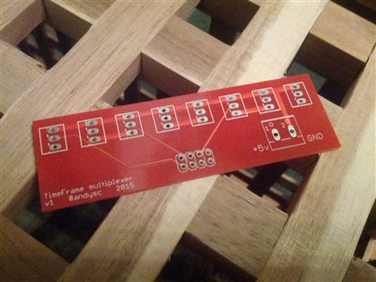
Then it was quite easy to convert that into a circuit board layout by dragging, rotating and dropping the components onto the circuit board. I used the auto-router to route the wires, though others have said that for a simple circuit it's just as easy to do the track routing by hand. Adding annotations like the labels on the screw terminals and a little descriptive text panel were a bit tricky to work out (you have to make sure it goes on the correct layer - the "tPlace" silkscreen layer). But soon the board passed the ERC (Electrical Rule Check) and DRC (Design Rule Check) quality control checkers, and I was ready to generate the Gerber files, following these instructions. I zipped up the resulting files and uploaded them to @ragworm for manufacturing.
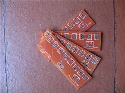
After a small hiccup with the processing of my order, my boards were made, and on their way back to me.
The pleasure of holding your first professionally made PCB is quite amazing
- if you've been thinking of taking the plunge on PCB design, I do recommend it!

I'll be using PCBs for most of my projects from now on! The next board will be the Arduino "shield" that I need to complete the TimeFrame project.
Parts list
Farnell Number | Description | Link |
2112013 | PSU 12V | |
1318719 | Power cord | |
2075382 | Arduino Uno | |
1196440 | Power cord | |
1109888 | PSU 5V | PCM50US05 - XP POWER - ADAPTOR, AC-DC, MEDICAL, 5V, 8A | Farnell element14 |
2075365 | MODULE, MICRO SERVO, TINKERKIT | |
9731156 | HEADER, SQUARE PIN, 2.54MM, 3WAY |
Special thanks to Model Fixings for supply of the size 0 screws I needed to attach the actuator arms to the wood blocks on the slats, and to the servos. Also thanks to the Arduino Store for supplying some of the Arduino 3-pin servo connectors needed for the multiplexer circuit boards.
Testing
At this point, I only had the Arduino-based control system that I built for the 4 slat prototype TimeFrame. So I worked my way along the 32 slats of the full-sized TimeFrame, connecting servos 4 at a time, overlapping by one each time, to check that the slats turned freely, and didn't bump into each other when they were at half travel (maximum width). One or two of the end bearings needed a squirt of WD-40. The wood stain had congealed in one or two of the bearing tubes, so that was carefully picked off with a sharp implement. But after that, all 32 slats turned elegantly and smoothly, and (most satisfyingly) there was no sign at all of the oscillating "jitter" than had dogged the prototype.
In Part 3, I'll describe the completion of the project, the electronic and software engineering phases, and include a video of the finished TimeFrame in operation!
Top Comments