element14 Community
element14 Community
    Register Log In
  • Site
  • Search
  • Log In Register
  • Members
    Members
    • Benefits of Membership
    • Achievement Levels
    • Members Area
    • Personal Blogs
    • Feedback and Support
    • What's New on element14
  • Learn
    Learn
    • Learning Center
    • eBooks
    • STEM Academy
    • Webinars, Training and Events
    • Learning Groups
  • Technologies
    Technologies
    • 3D Printing
    • Experts & Guidance
    • FPGA
    • Industrial Automation
    • Internet of Things
    • Power & Energy
    • Sensors
    • Technology Groups
  • Challenges & Projects
    Challenges & Projects
    • Design Challenges
    • element14 presents
    • Project14
    • Arduino Projects
    • Raspberry Pi Projects
    • Project Groups
  • Products
    Products
    • Arduino
    • Dev Tools
    • Manufacturers
    • Raspberry Pi
    • RoadTests & Reviews
    • Avnet Boards Community
    • Product Groups
  • Store
    Store
    • Visit Your Store
    • 'Choose another store...'
      • Europe
      •  Austria (German)
      •  Belgium (Dutch, French)
      •  Bulgaria (Bulgarian)
      •  Czech Republic (Czech)
      •  Denmark (Danish)
      •  Estonia (Estonian)
      •  Finland (Finnish)
      •  France (French)
      •  Germany (German)
      •  Hungary (Hungarian)
      •  Ireland
      •  Israel
      •  Italy (Italian)
      •  Latvia (Latvian)
      •  
      •  Lithuania (Lithuanian)
      •  Netherlands (Dutch)
      •  Norway (Norwegian)
      •  Poland (Polish)
      •  Portugal (Portuguese)
      •  Romania (Romanian)
      •  Russia (Russian)
      •  Slovakia (Slovak)
      •  Slovenia (Slovenian)
      •  Spain (Spanish)
      •  Sweden (Swedish)
      •  Switzerland(German, French)
      •  Turkey (Turkish)
      •  United Kingdom
      • Asia Pacific
      •  Australia
      •  China
      •  Hong Kong
      •  India
      •  Korea (Korean)
      •  Malaysia
      •  New Zealand
      •  Philippines
      •  Singapore
      •  Taiwan
      •  Thailand (Thai)
      • Americas
      •  Brazil (Portuguese)
      •  Canada
      •  Mexico (Spanish)
      •  United States
      Can't find the country/region you're looking for? Visit our export site or find a local distributor.
  • Translate
  • Profile
Personal Blogs
  • Members
  • More
Personal Blogs
Legacy Personal Blogs TPS54A20EVM evaluation - part 2
  • Blog
  • Documents
  • Mentions
  • Sub-Groups
  • Tags
  • More
  • Cancel
  • New
Blog Post Actions
  • Subscribe by email
  • More
  • Cancel
  • Share
  • Subscribe by email
  • More
  • Cancel
Group Actions
  • Group RSS
  • More
  • Cancel
Engagement
  • Author Author: jc2048
  • Date Created: 20 Dec 2016 9:55 AM Date Created
  • Views 384 views
  • Likes 2 likes
  • Comments 2 comments
Related
Recommended

TPS54A20EVM evaluation - part 2

jc2048
jc2048
20 Dec 2016

In this next part I'm going to look at the output on a static load.


Here's my output load:


image


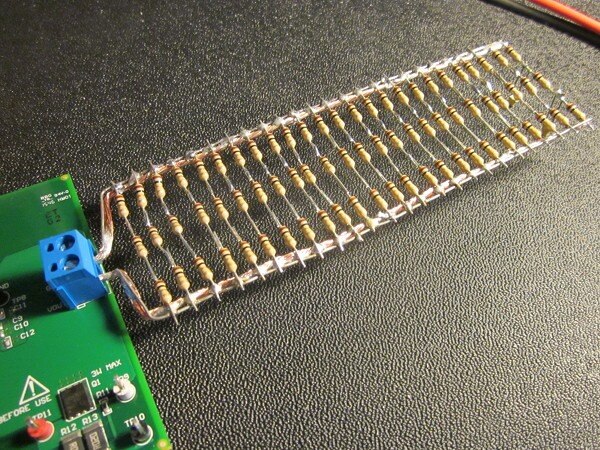
For 10A at 1.2V I need a load of 120 mOhms (1.2V/10A) and it has to be able to dissipate 12W (1.2V x 10A).

I made this up from cheap 1 ohm 0.25W resistors. Three resistors in series is 3 ohms; twenty-five of those in

parallel is then 120 mOhms. Each resistor only has to dissipate 160mW, so they're reasonably comfortable. It

measured 123 mOhms, so that will be an output current of something like 9.7A [it will move a bit when it heats up].


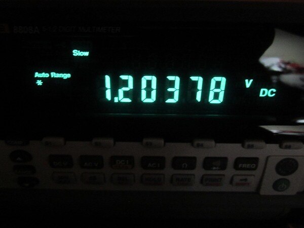
Here's the output voltage running the load. [Being a bit contrary, I'm running against the excellence-in-

photography tide.] That's fine - it's just 0.3% high.


image


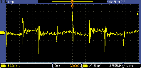
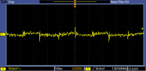
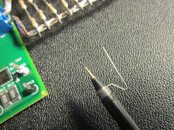
Next let's look at the output voltage ripple on load. The following two traces are of exactly the same signal - the first is using the probe's flying-lead ground and the second is using the spring clip ground. Both traces are ac coupled.


image


image


image


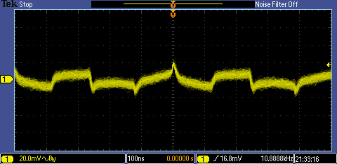
Next is the ripple with the bandwidth limited to 20MHz and accumulated traces. This nicely shows the underlying form of

the ripple and we can immediately see that there are four phases which presumably correspond to the phases that the

converter goes through, the spikes coming at the transitions which we would kind of expect.


image


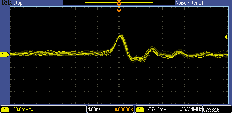
Finally here's one of the spikes. Unfortunately I'm right up against the limits of my scope here (200MHz,

1Gsps and passive probes). The rise time of the scope is going to be 1.7nS, or so, and that's what I'm seeing

here, so the spike itself is much faster and far taller. The peak on the trace is where the scope is scrabbling to catch up with the spike

when it's on its way down again. Essentially, I'm testing the response of the scope with an impulse waveform.


image

  • Sign in to reply

Top Comments

  • rachaelp
    rachaelp over 6 years ago +2
    You must have some patience to solder all those individual resistors together, that must have taken you ages! Very nice write up, it's good to see you showing the difference between using the long probe…
  • jc2048
    jc2048 over 6 years ago in reply to rachaelp +1
    No, it was quite fast. The resistors were on a bandolier, so I cropped one side and the band on the other then held them in place and gave the neat spacing. Went along and soldered them to a piece of tinned…
  • jc2048
    jc2048 over 6 years ago in reply to rachaelp

    No, it was quite fast. The resistors were on a bandolier, so I cropped one side and the band on the other then held them in place and gave the neat spacing. Went along and soldered them to a piece of tinned copper wire. Cropped the other side, repeated three times, final piece of wire along the other side and that was it. The advantage (other than spreading the heat, low-ish inductance, and the low cost - about 50p) is that I will be able to split it up and do transient testing between set currents (100% to 20%, and that kind of thing).

    • Cancel
    • Vote Up +1 Vote Down
    • Sign in to reply
    • More
    • Cancel
  • rachaelp
    rachaelp over 6 years ago

    You must have some patience to solder all those individual resistors together, that must have taken you ages!


    Very nice write up, it's good to see you showing the difference between using the long probe flying lead and the spring clip for grounding, the excessive bouncing around or spikes caused by using 6" of wire for the ground catches a lot of people out and they chase their tails trying to work out why their signals look so bad when in fact it's just their scope probe configuration.

    • Cancel
    • Vote Up +2 Vote Down
    • Sign in to reply
    • More
    • Cancel
element14 Community

element14 is the first online community specifically for engineers. Connect with your peers and get expert answers to your questions.

  • Members
  • Learn
  • Technologies
  • Challenges & Projects
  • Products
  • Store
  • About Us
  • Feedback & Support
  • FAQs
  • Terms of Use
  • Privacy Policy
  • Legal and Copyright Notices
  • Sitemap
  • Cookies

An Avnet Company © 2023 Premier Farnell Limited. All Rights Reserved.

Premier Farnell Ltd, registered in England and Wales (no 00876412), registered office: Farnell House, Forge Lane, Leeds LS12 2NE.

ICP 备案号 10220084.

Follow element14

  • X
  • Facebook
  • linkedin
  • YouTube