element14 Community
element14 Community
    Register Log In
  • Site
  • Search
  • Log In Register
  • Community Hub
    Community Hub
    • What's New on element14
    • Feedback and Support
    • Benefits of Membership
    • Personal Blogs
    • Members Area
    • Achievement Levels
  • Learn
    Learn
    • Ask an Expert
    • eBooks
    • element14 presents
    • Learning Center
    • Tech Spotlight
    • STEM Academy
    • Webinars, Training and Events
    • Learning Groups
  • Technologies
    Technologies
    • 3D Printing
    • FPGA
    • Industrial Automation
    • Internet of Things
    • Power & Energy
    • Sensors
    • Technology Groups
  • Challenges & Projects
    Challenges & Projects
    • Design Challenges
    • element14 presents Projects
    • Project14
    • Arduino Projects
    • Raspberry Pi Projects
    • Project Groups
  • Products
    Products
    • Arduino
    • Avnet & Tria Boards Community
    • Dev Tools
    • Manufacturers
    • Multicomp Pro
    • Product Groups
    • Raspberry Pi
    • RoadTests & Reviews
  • About Us
  • Store
    Store
    • Visit Your Store
    • Choose another store...
      • Europe
      •  Austria (German)
      •  Belgium (Dutch, French)
      •  Bulgaria (Bulgarian)
      •  Czech Republic (Czech)
      •  Denmark (Danish)
      •  Estonia (Estonian)
      •  Finland (Finnish)
      •  France (French)
      •  Germany (German)
      •  Hungary (Hungarian)
      •  Ireland
      •  Israel
      •  Italy (Italian)
      •  Latvia (Latvian)
      •  
      •  Lithuania (Lithuanian)
      •  Netherlands (Dutch)
      •  Norway (Norwegian)
      •  Poland (Polish)
      •  Portugal (Portuguese)
      •  Romania (Romanian)
      •  Russia (Russian)
      •  Slovakia (Slovak)
      •  Slovenia (Slovenian)
      •  Spain (Spanish)
      •  Sweden (Swedish)
      •  Switzerland(German, French)
      •  Turkey (Turkish)
      •  United Kingdom
      • Asia Pacific
      •  Australia
      •  China
      •  Hong Kong
      •  India
      • Japan
      •  Korea (Korean)
      •  Malaysia
      •  New Zealand
      •  Philippines
      •  Singapore
      •  Taiwan
      •  Thailand (Thai)
      • Vietnam
      • Americas
      •  Brazil (Portuguese)
      •  Canada
      •  Mexico (Spanish)
      •  United States
      Can't find the country/region you're looking for? Visit our export site or find a local distributor.
  • Translate
  • Profile
  • Settings
Personal Blogs
  • Community Hub
  • More
Personal Blogs
Legacy Personal Blogs TPS54A20EVM evaluation - part 3
  • Blog
  • Documents
  • Mentions
  • Sub-Groups
  • Tags
  • More
  • Cancel
  • New
  • Share
  • More
  • Cancel
Group Actions
  • Group RSS
  • More
  • Cancel
Engagement
  • Author Author: jc2048
  • Date Created: 27 Dec 2016 12:49 PM Date Created
  • Views 1039 views
  • Likes 6 likes
  • Comments 5 comments
Related
Recommended

TPS54A20EVM evaluation - part 3

jc2048
jc2048
27 Dec 2016

This is part three of evaluating a TPS54A20 on an evaluation board. The TPS54A20 is a buck converter with an

interesting topology - it has two phases merged with a switched-capacitor. This isn't a formal road test (I

was given the board by Jan Cumps, nice person that he is) and I'm just doing what interests me and blogging about

it. Disclaimer: some of what I do here is quite sloppy and, to be fair to TI, it shouldn't be taken as a

proper review.


This time it's transient output testing - what happens to the output voltage when the load changes suddenly.

In case it's not clear why anything happens, imagine a situation when a load of 10A is suddenly demanded from

the output. Initially, the only components that can supply the required current are the capacitors on the

output side. They are ceramic with low ESR and low inductance and will supply this kind of current, but as

soon as they do they start discharging and the voltage falls rapidly. The controller will then sense the fall

and act to bring the voltage back up, but that all takes a bit of time. This test isn't so much about what

happens in a real system, instead we're looking at how the control system responds - how stable is it and what

the damping is like, and questions like that.


My original idea for this was to switch my resistor load using a MOSFET, but then I realised that the board

includes a circuit to do this test. So, I've decided it would be interesting to do both and compare the

results.


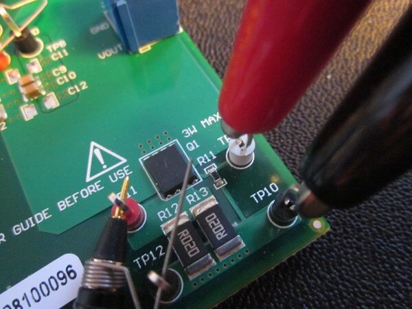
This is the circuit down in the corner of the board:


image


and here's the circuit diagram [copyright TI, I hope it constitutes fair use]:


image


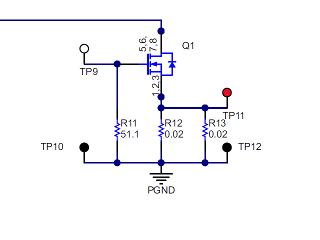
A major advantage of the inbuilt circuit is that (presumably) it was what they used when they were writing the

datasheet, so I'll have a point of comparison - my results should be roughly similar to theirs, except we

would hope that they have considerably better test equipment than I have. A second difference compared with my resistor

load, is that it should have lower inductance - the loops are much tighter and the planes naturally have low

inductance.


Curiously, the documentation doesn't tell you how to use the circuit, but it's fairly obvious I suppose. The

51R resistor at the gate is intended to take the signal from a waveform generator and the two 20mOhm resistors

in parallel are for current sensing - the combined 10mOhm giving 10mV per amp. The rest of the load resistance

comes from the MOSFET [it's just a matter of getting the Vgs right - the datasheet suggested 2.7V for 10A, but

I was seeing something a bit higher, around 3V]. I was slightly nervous that my ultra-cheap waveform generator

wouldn't give a precise enough output, but it was ok - rather than watch the generator waveform, I looked at

the current waveform and soon got used to bringing the current up to the level I wanted. The only other thing

to say is to make sure you have a reasonably long off period - I ran it 10:1 [a limitation of my poor signal

generator] and it seemed quite happy - if you don't, you'll exceed the dissipation limits of the MOSFET and

the resistors.


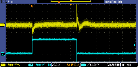
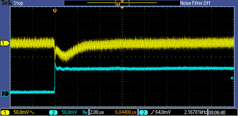
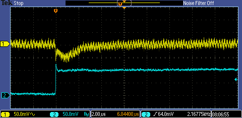
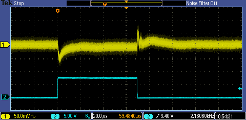
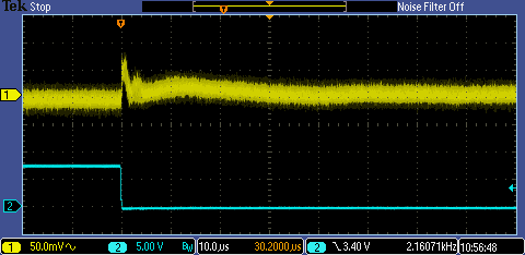
Here's what happens with a step to 10A. The blue trace is the current (100mV=10A, bandwidth limited to 20MHz),

the yellow trace is the output voltage, ac coupled, at the full bandwidth of the scope (200MHz). The step up

to 10A looks fine, the step down less well controlled.


image


For comparison, here's the trace that TI have in their datasheet:


image


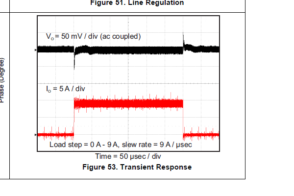
Curiously, my board seems better on the step up, but slightly worse coming down.


Here, in more detail, is the step up, first the accumulated trace and then a single trace. [The accumulated

trace shows the overall form nicely and the spread as the waveforms vary, the single one lets us see the

switching frequency that makes up the bulk of the noise.]


image

image


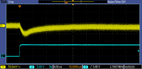
Here's the step down, which is less assured [again, accumulated first].


image

image


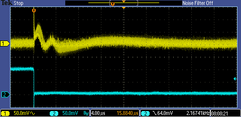
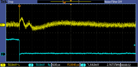
It takes quite a long period before it settles at the reference level, something that doesn't really show in

the trace on the datasheet. And there's quite a lot of variation at the start [where the accumulated trace broadens out].


Now for my transient test circuit. Here's the circuit diagram [yes, I know about these new-fangled CAD systems, but it's still quicker to draw it with a pen]:


image


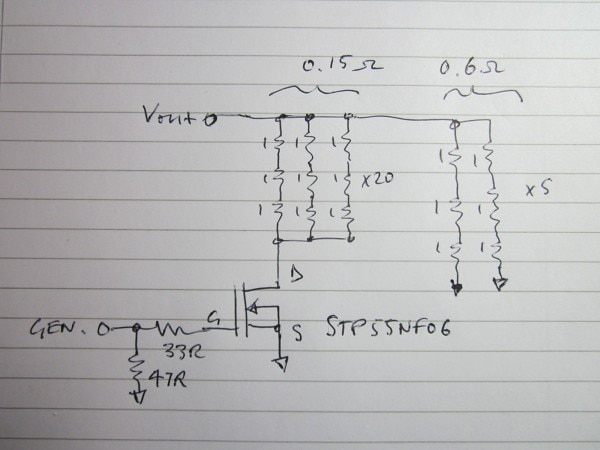
The choice of MOSFET was just what I had ready to hand. It would have been better to use one with a low Vgs threshold voltage - my generator

can only just get to the voltage this one needs to switch driving into 47ohms - but then I'd have had to search around for one. It needs to have a

low rDS on value, obviously, otherwise it will add too much to the resistor values. [Confession - I say obviously, but I had an IRF510 on a piece

of board, tried it, and then puzzled why it didn't work and would only go up to 2A or so. When I looked at the datasheet I realised it had an rDS-on of 0.56 ohms. How stupid is that?]


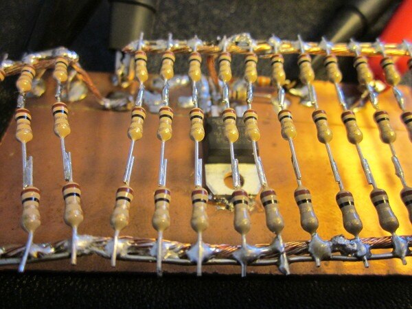
Here it is built on a piece of pcb board underneath the resistors (that's a good photo, some of the bits are in focus!). I've kept all the

wiring as short as possible to minimise inductance, though it will be a lot worse than TI's circuit.


image


Because the MOSFET has an 'on' resistance of a bit under 20mohm, the high current will be about 9A. The low current will be about 2A. Here are the waveforms.

The yellow trace is the voltage output. The blue is the generator waveform that's switching the MOSFET - it isn't showing us the current.


image


image


image


If you compare this to the measurement from the on-board circuit, it's not too much different in the broad view. There's a bit more difference in the

detailed views closer to the edges where the increased inductance will be having more of an effect. There's a bit more spread, but the shape still

gives us a good idea of how the control loop behaves itself.


I think it shows you can do a reasonable amount of testing like this with very simple equipment if you are sensible (and careful about how you interpret the results).

  • Sign in to reply

Top Comments

  • DAB
    DAB over 9 years ago +2
    Very good informative report. Well done. DAB
  • Jan Cumps
    Jan Cumps over 9 years ago +1
    Have you tried to get the efficiency? The advantage of this design seems to be that, with the series capacitor taking half of the stepdown duty and the inductor replaced by two inductors, the footprint…
  • jc2048
    jc2048 over 9 years ago in reply to Jan Cumps +1
    You're a hard taskmaster. And this is supposed to be my holiday too! That was going to be part 5 - input ripple is next, though I can skip straight to the efficiency if you want. You're right that it doesn…
  • jc2048
    jc2048 over 9 years ago in reply to Jan Cumps

    Your traces shouldn't look much different. The transient is taking place over several microseconds - if I put the 20MHz bandwidth limit on, it looks much the same except for a bit less noise. But do it anyway if you haven't already - their circuit is fun to play with.

    • Cancel
    • Vote Up 0 Vote Down
    • Sign in to reply
    • More
    • Cancel
  • Jan Cumps
    Jan Cumps over 9 years ago in reply to jc2048

    Jon Clift wrote:


    You're a hard taskmaster. And this is supposed to be my holiday too!


    I show no mercy image.


    I'm going to try the transient measures too. Not to check the device - you've done a great job a that.
    I want to see how it looks on a 50 MHz oscilloscope - what does a lower end sampling scope hide from you when measuring fast events...

    • Cancel
    • Vote Up 0 Vote Down
    • Sign in to reply
    • More
    • Cancel
  • jc2048
    jc2048 over 9 years ago in reply to Jan Cumps

    You're a hard taskmaster. And this is supposed to be my holiday too!


    That was going to be part 5 - input ripple is next, though I can skip straight to the efficiency if you want. You're right that it doesn't look too wonderful from the datasheet, but the physical size of the thing is amazing for something that can chuck out 10 amps. I've got into a routine where I set everything up and then turn it on - I don't probe around as it's running because there's too much danger I'll inadvertantly touch something (particularly with the spring-clip ground) and it's very easy to forget how much damage you might do. [The one change I'd make to the evaluation board is to have an LED where the power comes on to the board as a reminder that the power is on.]


    The transient response looks ok to me. It brings it back smartish. It's a bit skittish going off load, but I suppose it has to be to be agile, and presumably its unconditionally stable if you work to their guidelines on the decoupling. Having the 2MHz switching and the balanced channels looks advantageous there.

    • Cancel
    • Vote Up +1 Vote Down
    • Sign in to reply
    • More
    • Cancel
  • Jan Cumps
    Jan Cumps over 9 years ago

    Have you tried to get the efficiency?

    The advantage of this design seems to be that, with the series capacitor taking half of the stepdown duty and the inductor replaced by two inductors, the footprint of the design is low.

    The whole design fits in a tiny shallow space. On the other hand, it doesn't win the efficiency award, does it?

    • Cancel
    • Vote Up +1 Vote Down
    • Sign in to reply
    • More
    • Cancel
  • DAB
    DAB over 9 years ago

    Very good informative report.


    Well done.


    DAB

    • Cancel
    • Vote Up +2 Vote Down
    • Sign in to reply
    • More
    • Cancel
element14 Community

element14 is the first online community specifically for engineers. Connect with your peers and get expert answers to your questions.

  • Members
  • Learn
  • Technologies
  • Challenges & Projects
  • Products
  • Store
  • About Us
  • Feedback & Support
  • FAQs
  • Terms of Use
  • Privacy Policy
  • Legal and Copyright Notices
  • Sitemap
  • Cookies

An Avnet Company © 2025 Premier Farnell Limited. All Rights Reserved.

Premier Farnell Ltd, registered in England and Wales (no 00876412), registered office: Farnell House, Forge Lane, Leeds LS12 2NE.

ICP 备案号 10220084.

Follow element14

  • X
  • Facebook
  • linkedin
  • YouTube