


1/ the outputs (tractor lights - beacon, blinkers, lights)
I choose to use a Raspberry Pi for this task (Raspberry "Outputs" on the global sketch); I needed something independent of the PCs to lighten their processes and a board that can receive orders from TCP/IP. Fortunately, I didn't need more than 24 outputs.
So I have designed an extended board, with a voltage shifter (Txs0108e) (from 3.3V to 5V) to switch relays on a 8 relays module:

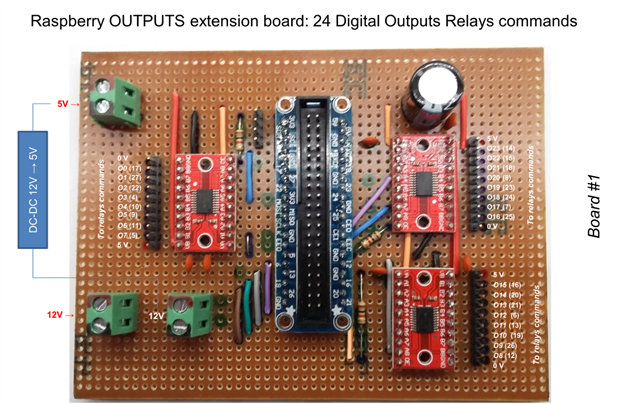


I have preferred to let the lights independent (I could have joined the right and left lights for example) to be able to play with lights animation (like chase effects) ...
I attached a 5" HDMI screen (it's tactile, but I don't use this function) to check the process progress.
As presented in part 1, the exhibition environment is very noisy. In previous projects, I had to face many interferences issues. So I add some "interference traps" to digital and analog signals.
2/ The digital chain
In a previous version, I had chosen a Raspberry PI with 4 x I2C MCP23017 extensions to manage all the digital inputs.
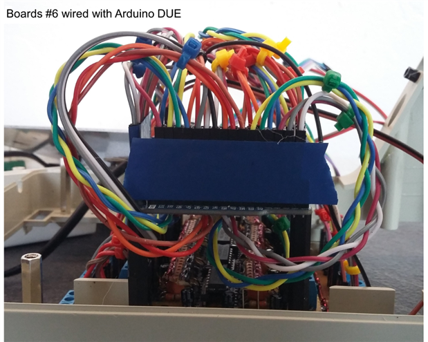
But I finally found that using an Arduino DUE would be much simpler. Moreover, it has ADCs too without any needed extensions.
And another advantage of the Arduino DUE (in addition to its execution speed) is the possibility to exploit interrupts for the digital inputs.
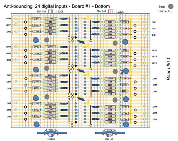
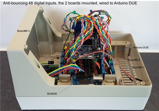
But to use this last feature, we need to robustify the signals, to avoid fake interrupts due to interferences. So I designed an anti-bouncing interface based on Schmitt trigger (SN74HC14N) (from here). Actually, I prefer hardware solution than software one that slows down a program.
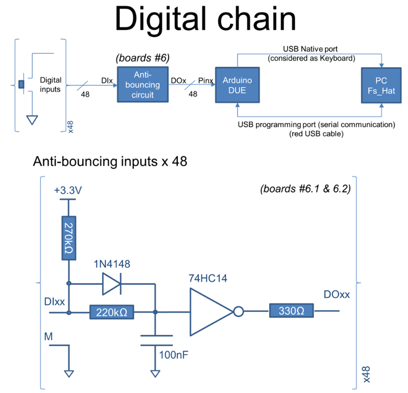
Then the Arduino DUE (and it's the final advantage of it) will translate an input to a key or sequence of keys simulating a keyboard for the "FS Hat" PC.
I have also 6 signals (among the 48) coming from the armrest powered in 3.3V I will use optocouplers.


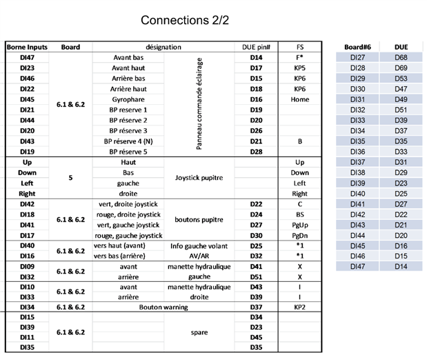
(sorry, in French, but it's all the buttons, levers and controllers we can find in a tractor)
During the developping progress, I needed to add another anti-bouncing system, just one, te be read by an arduino UNO (see later); its the "up" position of the tire (position at the end of the day, for the night, to release the jacks).
I didn't want to use a 74HC14 just for 1 gate. So I designed this with a NE555 (from here):

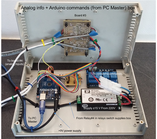
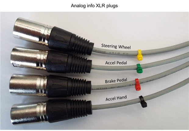
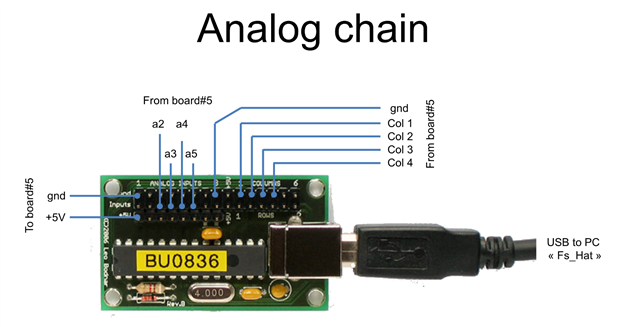
3/ The analog signals (steering wheel, brakes and acceleration pedals, hand accelerator)
My first experience was to power the potentiometers with 0-3.3V to be able to read the values directly with an ADC (I had first used a raspberry pi with a MCP3208 - 8 channels, 12 bits resolution, SPI link). But the rotations of the pedals are very small and the resulting range was very poor (ie. about 200 points amoung 4096 available (12 bits resolution) once digitalized) and so very sensitive to interferences.
So, I decided to power them with a larger range of tension from +/- 15V. I use a LM324 that accepts this range of voltage to buffer a simple voltage divider to the potentiometer.
Then, I added protections and filters before Arduino DUE ADC. I had prefered using PWM instead of DAC as firstly I need 4 outputs (only 2 DACs on DUE), and secondly the embedded DAC range is not full 0-3.3V!
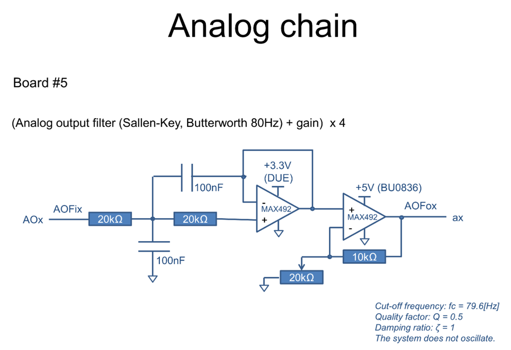
Thus, I added the same filter as the inputs (to filter the PWM signals) and a gain (from 3.3V to 5V) to feed the BU0836A (the joystick/analog entries USB-plugged on the PC "FS Hat").

The analog info are sent to PC "FS Hat" too for them to be transfered to Rasperry "Dashboard" (front wheels angles following the steering wheel angle, displayed speed vs the acceleration, brakes lights, back-up lights ...)

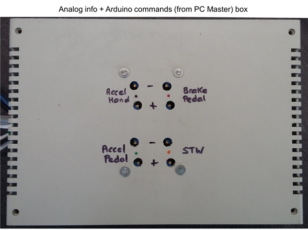
The range tuning (0-3.3V) is quite easy when you first observe the initial range; you feel how to turn the potentiometers +/- to reach the requested values once you have an idea of the min, max and range.
But you really need SOMEONE to turn the steering wheel, push the pedals and turn the hand accelerator while you are measuring the ranges with a multimeter !!! 


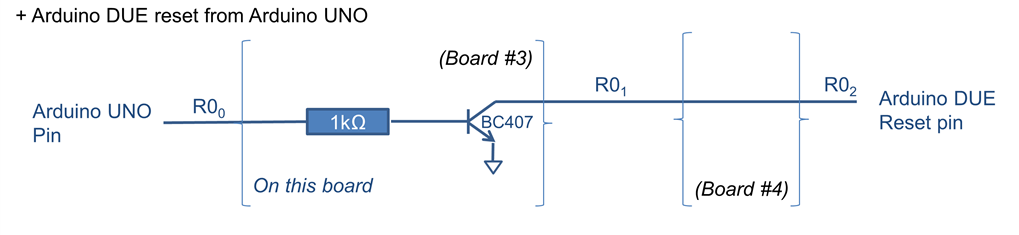
Note: in the middle of the board, I add a line for the arduino UNO (connected to PC "Master") to hard reset the Arduino DUE (so far, I never used it)

As the info come from the front of the cabin and the signal processing is at the rear, even if it's wired with shielded cables, I add a low-pass filter with a protection part (avoiding putting more than 3.3V on an arduino pin) .
Initially, I intended to choose 60Hz of bandwidth as it corresponds to the refresh rate of a screen and it's wide enough to take into account a signal change (have in mind that in real life, an ABS brakes reaction time is around 300ms ... so far from the chosen 16ms reaction time).
However, to reach that figure, it required not common values of resistors and capacitors. So, I look at this tool to compute Sallen-Key components for 60Hz, then I took the closest common values, and compute again with these common components and the results leaded to 79.6Hz (80Hz). Ok.

Note : I power the LM358 with 5.3V as the output is -2V lower vs the power and support up to 30V inputs (not a rail-to-rail opAmp). However, I use a rail-to-rail MAX492 for the final output.


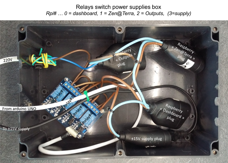
4/ the supplies

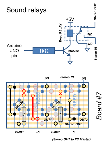
5/ miscelleous


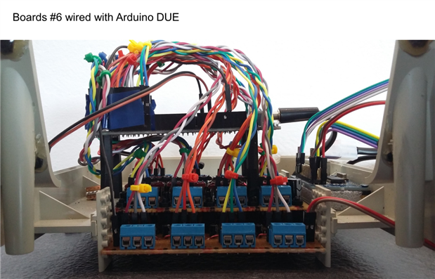
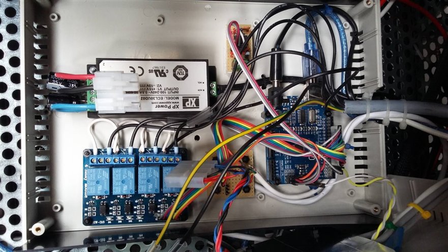
Fully wired:

Back to intro
Tractor Simulator (interface with Farming Simulator 17)
Global presentation
Tractor simulator (cabin tractor interface with Farming Simulator 17): Part 1 - global presentation
Actual doc
Arduinos
Raspberry Pis
PCs
Tractor simulator (cabin tractor interface with Farming Simulator 17): Part 3 - the software, 3/ PCs
Top Comments