element14 Community
element14 Community
    Register Log In
  • Site
  • Search
  • Log In Register
  • About Us
  • Community Hub
    Community Hub
    • What's New on element14
    • Feedback and Support
    • Benefits of Membership
    • Personal Blogs
    • Members Area
    • Achievement Levels
  • Learn
    Learn
    • Ask an Expert
    • eBooks
    • element14 presents
    • Learning Center
    • Tech Spotlight
    • STEM Academy
    • Webinars, Training and Events
    • Learning Groups
  • Technologies
    Technologies
    • 3D Printing
    • FPGA
    • Industrial Automation
    • Internet of Things
    • Power & Energy
    • Sensors
    • Technology Groups
  • Challenges & Projects
    Challenges & Projects
    • Design Challenges
    • element14 presents Projects
    • Project14
    • Arduino Projects
    • Raspberry Pi Projects
    • Project Groups
  • Products
    Products
    • Arduino
    • Avnet Boards Community
    • Dev Tools
    • Manufacturers
    • Multicomp Pro
    • Product Groups
    • Raspberry Pi
    • RoadTests & Reviews
  • Store
    Store
    • Visit Your Store
    • Choose another store...
      • Europe
      •  Austria (German)
      •  Belgium (Dutch, French)
      •  Bulgaria (Bulgarian)
      •  Czech Republic (Czech)
      •  Denmark (Danish)
      •  Estonia (Estonian)
      •  Finland (Finnish)
      •  France (French)
      •  Germany (German)
      •  Hungary (Hungarian)
      •  Ireland
      •  Israel
      •  Italy (Italian)
      •  Latvia (Latvian)
      •  
      •  Lithuania (Lithuanian)
      •  Netherlands (Dutch)
      •  Norway (Norwegian)
      •  Poland (Polish)
      •  Portugal (Portuguese)
      •  Romania (Romanian)
      •  Russia (Russian)
      •  Slovakia (Slovak)
      •  Slovenia (Slovenian)
      •  Spain (Spanish)
      •  Sweden (Swedish)
      •  Switzerland(German, French)
      •  Turkey (Turkish)
      •  United Kingdom
      • Asia Pacific
      •  Australia
      •  China
      •  Hong Kong
      •  India
      •  Korea (Korean)
      •  Malaysia
      •  New Zealand
      •  Philippines
      •  Singapore
      •  Taiwan
      •  Thailand (Thai)
      • Americas
      •  Brazil (Portuguese)
      •  Canada
      •  Mexico (Spanish)
      •  United States
      Can't find the country/region you're looking for? Visit our export site or find a local distributor.
  • Translate
  • Profile
  • Settings
Personal Blogs
  • Community Hub
  • More
Personal Blogs
Legacy Personal Blogs Transistors: The Astable Multivibrator (Featuring SuperLEDman).
  • Blog
  • Documents
  • Mentions
  • Sub-Groups
  • Tags
  • More
  • Cancel
  • New
  • Share
  • More
  • Cancel
Group Actions
  • Group RSS
  • More
  • Cancel
Engagement
  • Author Author: jc2048
  • Date Created: 17 Mar 2018 12:57 PM Date Created
  • Views 2662 views
  • Likes 15 likes
  • Comments 14 comments
  • circuits
  • superheroes
  • transistors
Related
Recommended

Transistors: The Astable Multivibrator (Featuring SuperLEDman).

jc2048
jc2048
17 Mar 2018

I'm still very short of time, so this blog is just a quick, simple one.


Well, it had to happen eventually, here I am doing the astable multivibrator (an oscillator circuit).


This is going to be in two parts. First a look at the circuit in the simulator and then I'm going to build one. That second

part will be a trip down memory lane for me because this is the first circuit I ever built and I'm going to have a go at

recreating, in a modern form, what I did back then. More on that in a moment.


Here is the schematic as I've simulated it - it's also what I'm going to build later on. It's not as elegant as the beautiful

hand-drawn sketch that I showed in the previous 'Transistors' blog on the Ho Serial Astable, but it will do. I've added

various test meters around the circuit so we can see what is going on.


image


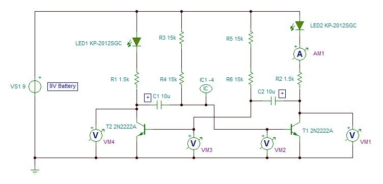
The supply I've chosen as being 9V so that I can run it on a PP3 (SF22) battery. The LEDs in the circuit are just a random

selection from those available in the simulator - in the real thing I'm going to use small red LEDs with a forward voltage

of around 2V. The capacitors are 10uF electrolytics and need to be the right way round - I've marked the positive end (the

simulator doesn't have a proper symbol for a polarised capacitor). The voltage rating of the capacitors needs to be greater

than 9V; 16V or higher would be fine. The transistors are 2N2222A parts from CDIL. If you want to build one, you could

probably get it to work with almost any small NPN transistor - just try whatever you have handy and see what happens. I

chose the 2N2222A simply because it was available for a reasonable price in a metal TO18 can and I thought would look nice

in the final build.


In case you're wondering what IC1 on the circuit is, it's not a component at all; it's an initial condition. It's just there

to get the oscillator started. Unlike real life, where start-up noise would get the oscillator oscillating, the simulated

version needs a kick otherwise it just sits there with the two sides perfectly balanced.


Here are the waveforms that result


image


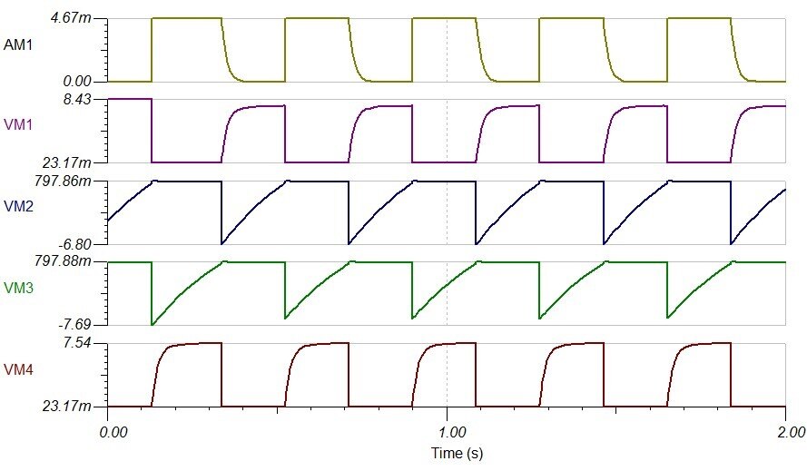
Analysing the circuit purely from the schematic is quite tricky. Where do you start? The symmetry means there is no input as

such, instead each side makes a change and triggers some response on the other side. What helps us is seeing the waveforms.

We can see that what happens at the base of transistor T2 (VM3) is the same as what happens at the base of T1 (VM2) except

that there's a time delay involved. We might also suspect that each follows on from the other. Similarly, the waveforms at

the two collectors (VM1 and VM4) are the same except for a shift in time and align with the previous two. We can also see

where the delay is coming from on the VM2 and VM3 waveforms - the upward slope is characteristic of a capacitor charging and

the circuit is waiting for a certain voltage (somewhere around 800mV in each case) to be reached before operation continues.


Perhaps take that and see if you can work out how it operates. (Helpful hint: you can't instantaneously change the voltage

across a capacitor - if you step the voltage on one side, you'll see the same step on the other.)


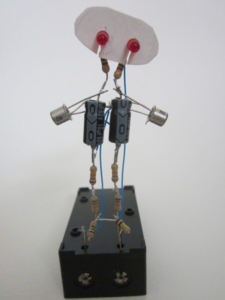
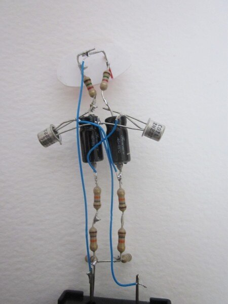
Now for building it. Instead of using a prototyping block or a circuit board, I'm just going to solder the components

together. The original used torch bulbs, electrolytics and resistors which were larger than moderen equivalents, and

transistors that, at that time, were packaged in small metal capsules. This version is about half the size.


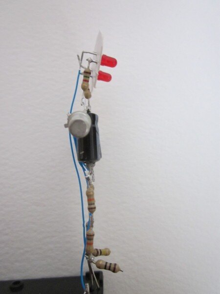
Here are pictures taken from the front, back, and side. The resistors for the feet are just decoration and can be any value.

The base is a 9V battery box; it's the kind intended for PCB mounting and I've got it upside down, with the circuit board

leads pointing up. The weight of the battery makes for a resaonable base. The arms are a bit short - if I did it again, I

might consider extending them. I decided that it needed a face, so cut a simple shape out of cardboard that just sits on the

LED leads.


image

image

image


Finally, here it is working. The proof that Super-LED-man can flash his eyes (and that I can't hold a camera still).


You don't have permission to edit metadata of this video.
Edit media
x
image
Upload Preview
image


Final question: why is this technically a bad circuit?

  • Sign in to reply

Top Comments

  • jc2048
    jc2048 over 7 years ago in reply to dougw +7
    The face plate can easily be customised. Here's another example that I did: I think I'll leave the Star Wars characters to someone else. I built the original when I was given a soldering iron as a Christmas…
  • dougw
    dougw over 7 years ago +5
    Nice demo circuit. Brings back memories - one of those early milestones of understanding. Add a little hoodie and you have a Jawa.
  • jw0752
    jw0752 over 7 years ago +5
    Hi Jon, I really like these blogs with a circuit, a build, and a lesson. I will make a note and play with your circuit as soon as I get caught up. John
  • mcb1
    mcb1 over 7 years ago

    Nice easy demo.


    I might have to take a photo tomorrow of my antex iron that I've had for 40 or so years ... I think.


    Mark

    • Cancel
    • Vote Up +2 Vote Down
    • Sign in to reply
    • More
    • Cancel
  • jc2048
    jc2048 over 7 years ago in reply to shabaz

    I was curious about the capacitor. Most datasheets don't seem to give a value, but I found this one from Vishay which does and they seem to be happy with up to one volt reverse voltage. With the astable it won't exceed the Vbe-on voltage less the saturation voltage of the other transistor, and that's going to result in something like half a volt, so it looks like we're fairly safe.


    image

    • Cancel
    • Vote Up +2 Vote Down
    • Sign in to reply
    • More
    • Cancel
  • Jan Cumps
    Jan Cumps over 7 years ago in reply to jc2048

    image

    • Cancel
    • Vote Up +2 Vote Down
    • Sign in to reply
    • More
    • Cancel
  • jc2048
    jc2048 over 7 years ago in reply to shabaz

    They came from Rapid.


    https://www.rapidonline.com/catalogue/search?Query=2n2222


    I live within walking distance of their trade counter and the minimum order for collection is only £1, so it's an easy way to get small quantities of common parts for personal projects. Their range of parts isn't that extensive, though.


    CDIL are interesting. They are an Indian foundry and seem to be stepping into the area vacated by the traditional semi manufacturers steadily abandoning this kind of conventional packaging.


    I hadn't thought about the capacitors. The 'homework' question was more to do with the base voltage: on a supply of 9V, the base exceeds the reverse Vbe rating (usually 5V or 6V is quoted on a datasheet). So, technically, we're outside the datasheet. In practice there's no problem because the actual breakdown voltage is more like 8V, but you shouldn't do it with a commercial design. It becomes more of a problem with higher supply voltages - in the old days, there were various ways to mitigate the problem; one way, if you weren't worried about the floor of the collector waveform, was to simply put a signal diode in series with the emitter (the reverse Vbe then becomes the transistor plus the diode, which can be several hundred volts).

    • Cancel
    • Vote Up +4 Vote Down
    • Sign in to reply
    • More
    • Cancel
  • jc2048
    jc2048 over 7 years ago in reply to Jan Cumps

    image

    • Cancel
    • Vote Up +2 Vote Down
    • Sign in to reply
    • More
    • Cancel
>
element14 Community

element14 is the first online community specifically for engineers. Connect with your peers and get expert answers to your questions.

  • Members
  • Learn
  • Technologies
  • Challenges & Projects
  • Products
  • Store
  • About Us
  • Feedback & Support
  • FAQs
  • Terms of Use
  • Privacy Policy
  • Legal and Copyright Notices
  • Sitemap
  • Cookies

An Avnet Company © 2025 Premier Farnell Limited. All Rights Reserved.

Premier Farnell Ltd, registered in England and Wales (no 00876412), registered office: Farnell House, Forge Lane, Leeds LS12 2NE.

ICP 备案号 10220084.

Follow element14

  • X
  • Facebook
  • linkedin
  • YouTube