element14 Community
element14 Community
    Register Log In
  • Site
  • Search
  • Log In Register
  • Community Hub
    Community Hub
    • What's New on element14
    • Feedback and Support
    • Benefits of Membership
    • Personal Blogs
    • Members Area
    • Achievement Levels
  • Learn
    Learn
    • Ask an Expert
    • eBooks
    • element14 presents
    • Learning Center
    • Tech Spotlight
    • STEM Academy
    • Webinars, Training and Events
    • Learning Groups
  • Technologies
    Technologies
    • 3D Printing
    • FPGA
    • Industrial Automation
    • Internet of Things
    • Power & Energy
    • Sensors
    • Technology Groups
  • Challenges & Projects
    Challenges & Projects
    • Design Challenges
    • element14 presents Projects
    • Project14
    • Arduino Projects
    • Raspberry Pi Projects
    • Project Groups
  • Products
    Products
    • Arduino
    • Avnet Boards Community
    • Dev Tools
    • Manufacturers
    • Multicomp Pro
    • Product Groups
    • Raspberry Pi
    • RoadTests & Reviews
  • About Us
  • Store
    Store
    • Visit Your Store
    • Choose another store...
      • Europe
      •  Austria (German)
      •  Belgium (Dutch, French)
      •  Bulgaria (Bulgarian)
      •  Czech Republic (Czech)
      •  Denmark (Danish)
      •  Estonia (Estonian)
      •  Finland (Finnish)
      •  France (French)
      •  Germany (German)
      •  Hungary (Hungarian)
      •  Ireland
      •  Israel
      •  Italy (Italian)
      •  Latvia (Latvian)
      •  
      •  Lithuania (Lithuanian)
      •  Netherlands (Dutch)
      •  Norway (Norwegian)
      •  Poland (Polish)
      •  Portugal (Portuguese)
      •  Romania (Romanian)
      •  Russia (Russian)
      •  Slovakia (Slovak)
      •  Slovenia (Slovenian)
      •  Spain (Spanish)
      •  Sweden (Swedish)
      •  Switzerland(German, French)
      •  Turkey (Turkish)
      •  United Kingdom
      • Asia Pacific
      •  Australia
      •  China
      •  Hong Kong
      •  India
      •  Korea (Korean)
      •  Malaysia
      •  New Zealand
      •  Philippines
      •  Singapore
      •  Taiwan
      •  Thailand (Thai)
      • Americas
      •  Brazil (Portuguese)
      •  Canada
      •  Mexico (Spanish)
      •  United States
      Can't find the country/region you're looking for? Visit our export site or find a local distributor.
  • Translate
  • Profile
  • Settings
Personal Blogs
  • Community Hub
  • More
Personal Blogs
Legacy Personal Blogs Transistors: The Transistor as a Switch
  • Blog
  • Documents
  • Mentions
  • Sub-Groups
  • Tags
  • More
  • Cancel
  • New
  • Share
  • More
  • Cancel
Group Actions
  • Group RSS
  • More
  • Cancel
Engagement
  • Author Author: jc2048
  • Date Created: 13 Jan 2017 12:00 PM Date Created
  • Views 6280 views
  • Likes 9 likes
  • Comments 30 comments
Related
Recommended

Transistors: The Transistor as a Switch

jc2048
jc2048
13 Jan 2017

I've been getting interested in designing with transistors recently, so I thought I'd start blogging about some of the things that I'm doing as I learn. This blog is about using the transistor as a switch. Specifically, I'm going to look at how it behaves at high speed and at a couple of traditional methods for speeding up the switching (what I'm considering here isn't really an issue if you are switching a load slowly or something like that).


Here's the circuit diagram of my experimental circuit. I needed a pulse generator that could give fast, clean edges and happened to have an Arduino board not doing anything, so I used that. The transistor is a common, NPN, general-purpose type: a 2N3904. I'm using 9V from a bench PSU as the supply and it also powers the Arduino - that way I have a single on/off switch to isolate everything when I want to do some soldering.


image


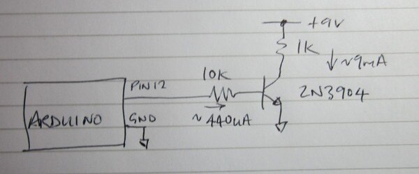
I built the circuit on a scrap of PCB material. The fat traces give low inductance and since there's no plane underneath there is little capacitance between the components or to ground. It's not what you would want for a product, where a ground plane gives consistency, turns traces into something like transmission lines and 'shields' traces because of the tight way electric fields arrange themselves, but it suits what I'm doing here. Although I haven't shown it on the circuit, I've decoupled the +9V supply with a 10uF electrolytic and a small 0805 100nF ceramic capacitor.


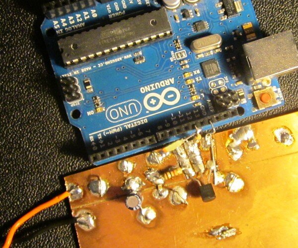
Here's what it looks like [I suspect this picture might win an award for Worst Blog Photograph of the Year - the black blob is the transistor, in case you're not sure what you're looking at]:


image


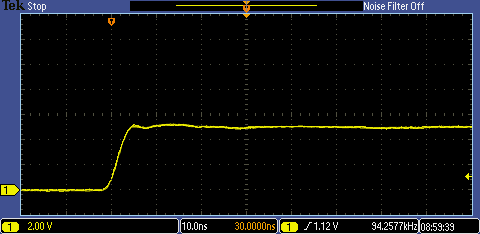
First let's look at the Arduino output by itself. I've done these with a spring-clip ground, rather than the flying-lead ground on the scope probe. You can see that the output is reasonably well behaved. The rise and fall times are about 4nS. My scope has a rise time of about 3.5nS (200MHz bandwidth), so they're about right for what I can deal with doing this experiment and it's plenty fast enough for the transistor I've selected.


imageimage


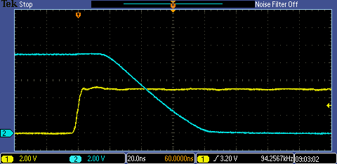
This next trace shows the collector waveform when the transistor turns on. The yellow trace is the Arduino output, the blue one is the collector. (Note that the horizontal scale is changing in all of these - sorry, it's just force of habit to adjust the scope to give the best detail rather than try and maintain consistency. The white figure is the timebase - in the case of the next one it's 10nS/division - the orange figure is there to confuse you if you look quickly - it's the time that the trigger point is ahead of the display centre.) Here we can see that the transistor is slow to turn on - there's a delay of about 20nS (the 'delay time') before anything occurs and then it takes what seems to be forever to pull the collector down, the fall time being about 60ns (that one is properly known as the 'rise time' because the transistor parameter is the rise in the collector current).


image


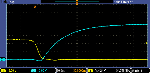
Well, if you think that one's slow, have a look at the turn-off time


image


Yes, nothing at all happens for 400nS (known as the 'storage time') and then it takes a leisurely 300nS to get where it's going (the 'fall time' as this time the collector current is falling). What a lazy device - it's surprising it can manage to get out of bed in the morning.


So why all these delays and can we do better than this?


Starting at the beginning, with the Arduino pin at 0V, the base of the transistor will also be at 0V. When the Arduino pin goes high, the first thing that has to happen is that the internal capacitances within the transistor (Cbe and Cbc) have to charge. They do that through the 10k base resistor and the initial delay time is the time it takes to get the base up to around 0.6V where the transistor will start to turn on. At that point, charged carriers start to accumulate on the base and the collector current starts to increase in proportion. Eventually, the collector voltage falls below the base voltage, and as it approaches zero the base-collector diode becomes forward biassed and the base injects carriers in to the collector region - this is called saturation.


When it comes to turning the transistor off, all those charges in the collector region have to be removed first (through a reverse current flowing out of the base) before the base charges can be removed and the collector current reduced.


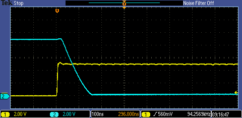
One obvious way to speed up the process is to increase the base current massively, however that wastes a lot of power when the high current is only needed at the switching transitions. An alternative way to get the same result is to place a small capacitor (called a 'speed-up' capacitor) across the 10k resistor. Here is what the waveforms look like with a 68pF in parallel with the 10k.


8 89imageimage


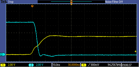
This has reduced the delay time to 2 or 3nS and the rise time to about 5nS. The storage time looks to be about 5nS and the fall time 40 or 50nS.

One thing to notice is that this is quite hard work for the Arduino output pin - on the way up you can see that, when it gets to the point where the transistor starts to turn on, it's suddenly having to drive a much higher current. It doesn't matter, the average dissipation is low, but it will be testing the Arduino's decoupling.


Another method of speeding things up is slightly less obvious and that's to stop the transistor saturating in the first place. That will remove the storage time, though the other delays will still be there. Since the saturation occurs after the base-collector diode forward biasses, if we place a diode between the base and collector, with a lower Vf than that junction has, then it will conduct first and stop the collector from falling any further. The obvious diode to do that is a Schottky. Here are the circuit and waveforms without a speed-up capacitor and with a BAT42 from base to collector.


image


imageimage


This does remove the storage time, but the following fall time is longer. That's because we now have the diode capacitance added to what is internal to the transistor. So nowhere near  the value we get from the speed-up capacitor. The technique has been used in the past; low-power Schottky logic used this technique to get the same speed as standard TTL but with lower currents.


Finally, a few more words about the speed-up capacitor.


Here are the base waveforms with the 68pF speed-up capacitor


image


In this case the capacitor is larger than is necessary to simply remove the necessary charge when we turn off the transistor so we end up with a negative voltage on the base that then slowly charges back to 0V through the 10k base resistor. That doesn't hurt the transistor - the max negative Vbe figure is usually given as 5V or 6V - but it does mean that if the next turn on happens during that period, it will take longer to bring the base up to the 0.6V where the transistor turns on, so the delay time will be longer.


There's a second snag which I'll mention, though not look at. I've seen application notes that show, with a critical value of capacitor that's not quite up to extracting all the stored charge, you can get a situation where the falling collector current reverses and goes up again momentarily so the collector voltage isn't monotonic and has a kink in it. That might then give you problems if the output were driving a clock input.

  • Sign in to reply

Top Comments

  • jc2048
    jc2048 over 8 years ago +6
    This is a follow-up the the blog above. Here I'm going to implement a constant-current source to replace the 1k collector load resistor to see if it will do a better job. This was at the suggestion of…
  • jc2048
    jc2048 over 8 years ago in reply to D_Hersey +5
    Me not putting in enough effort? Thanks! The mirror will have the same problem as the current source and waste more power (9mA down each side). To me, it seems a bit silly to use a $3 op-amp to speed up…
  • jc2048
    jc2048 over 8 years ago in reply to pettitda +4
    I'm genuinely trying to learn about the design of transistor circuits (out of interest and curiosity, rather than because I need to), but yes, I've cheated a little. I know the device theory (at least…
Parents
  • jc2048
    jc2048 over 8 years ago

    This is a follow-up the the blog above. Here I'm going to implement a constant-current source to replace the 1k collector load resistor to see if it will do a better job. This was at the suggestion of D_Hersey  in his comment above.


    Here's the circuit diagram. The circuit replaces the 1k collector resistor I had in the original circuit, so the collectors of the two transistors join together.


    image


    And here's the circuit as I built it. Beauty is in the eye of the beholder as they say and I say it's beautiful (feel free to differ if you want to - either way it will do the job).


    image


    I better quickly say what it does, since it may not be obvious. The potential divider roughly splits the supply, giving a base voltage of something like 4.5V (in practice it will be a little higher because the transistor base will source some current). The emitter follower 2N3906 follows that voltage giving a voltage at the bottom of the 470 of somewhere just above 5V. That then means the 470 has a constant voltage across it and a current of approximately 9mA will flow through it. Most of that current will find its way to the collector, giving us our constant current source.


    The 47n capacitor is there because I discovered that, when the switch turned on, the base-emitter capacitance in the 2N3906 was such that the base was pulled all the way down to ground before recovering again. The capacitor counters that. With a 47n it just twitches slightly - in a practical circuit you'd probably choose a value a bit larger (I just used what was quickly to hand in the clutter on the bench).


    Now for the results.


    imageimage


    And here are the original  traces with the 1k load resistor as a comparison (watch out for the different horizontal speed in the one on the right above).


    imageimage


    Now that we have a constant current going, it's evident that all of the transistor fall time, when the switch turns off, comes from capacitance - the previous exponential is now a nice linear ramp (though it starts to deviate a bit above 5V when the current source stops regulating the current properly).


    Unfortunately, the constant current source doesn't really help at all. The capacitance of the collector of the PNP transistor combines with that of the NPN switching transistor to give an longer fall time even though it's now being charged more efficiently. Admittedly, we could increase the current, but we could do that with the resistor too without all the extra circuit complexity.


    Final note. The constant current generator isn't too stable and is getting thrown around - here's an accumulated trace:


    image

    • Cancel
    • Vote Up +6 Vote Down
    • Sign in to reply
    • More
    • Cancel
Comment
  • jc2048
    jc2048 over 8 years ago

    This is a follow-up the the blog above. Here I'm going to implement a constant-current source to replace the 1k collector load resistor to see if it will do a better job. This was at the suggestion of D_Hersey  in his comment above.


    Here's the circuit diagram. The circuit replaces the 1k collector resistor I had in the original circuit, so the collectors of the two transistors join together.


    image


    And here's the circuit as I built it. Beauty is in the eye of the beholder as they say and I say it's beautiful (feel free to differ if you want to - either way it will do the job).


    image


    I better quickly say what it does, since it may not be obvious. The potential divider roughly splits the supply, giving a base voltage of something like 4.5V (in practice it will be a little higher because the transistor base will source some current). The emitter follower 2N3906 follows that voltage giving a voltage at the bottom of the 470 of somewhere just above 5V. That then means the 470 has a constant voltage across it and a current of approximately 9mA will flow through it. Most of that current will find its way to the collector, giving us our constant current source.


    The 47n capacitor is there because I discovered that, when the switch turned on, the base-emitter capacitance in the 2N3906 was such that the base was pulled all the way down to ground before recovering again. The capacitor counters that. With a 47n it just twitches slightly - in a practical circuit you'd probably choose a value a bit larger (I just used what was quickly to hand in the clutter on the bench).


    Now for the results.


    imageimage


    And here are the original  traces with the 1k load resistor as a comparison (watch out for the different horizontal speed in the one on the right above).


    imageimage


    Now that we have a constant current going, it's evident that all of the transistor fall time, when the switch turns off, comes from capacitance - the previous exponential is now a nice linear ramp (though it starts to deviate a bit above 5V when the current source stops regulating the current properly).


    Unfortunately, the constant current source doesn't really help at all. The capacitance of the collector of the PNP transistor combines with that of the NPN switching transistor to give an longer fall time even though it's now being charged more efficiently. Admittedly, we could increase the current, but we could do that with the resistor too without all the extra circuit complexity.


    Final note. The constant current generator isn't too stable and is getting thrown around - here's an accumulated trace:


    image

    • Cancel
    • Vote Up +6 Vote Down
    • Sign in to reply
    • More
    • Cancel
Children
No Data
element14 Community

element14 is the first online community specifically for engineers. Connect with your peers and get expert answers to your questions.

  • Members
  • Learn
  • Technologies
  • Challenges & Projects
  • Products
  • Store
  • About Us
  • Feedback & Support
  • FAQs
  • Terms of Use
  • Privacy Policy
  • Legal and Copyright Notices
  • Sitemap
  • Cookies

An Avnet Company © 2025 Premier Farnell Limited. All Rights Reserved.

Premier Farnell Ltd, registered in England and Wales (no 00876412), registered office: Farnell House, Forge Lane, Leeds LS12 2NE.

ICP 备案号 10220084.

Follow element14

  • X
  • Facebook
  • linkedin
  • YouTube