


Somewhere on the front panel of almost any oscilloscope is a "Cal" reference signal output (Figure 1). That signal is really intended for adjusting the capacitance compensation screw to calibrate a 10X high-impedance probe, but most of us know it simply as the Cal signal. Have you ever noticed that the Cal signal's rise time seems to be highly dependent on the length of the cable attached to it, and maybe even wondered why?

Figure 1: All oscilloscopes have a Cal output like the one pictured here
If so, you've come to the right place, because in this and ensuing posts, we'll explore this phenomenon and what causes it as we dive into transmission lines and their implications for you as oscilloscope users.
Let's take a look at this Cal signal, which is a nominal 1-V pk-pk square wave (Figure 2). Say we attach a 3' long RG-174 50-Ω coaxial cable to an oscilloscope's Cal output and use our instrument's parameter measurement capabilities to record the 10-90% rise time. In doing so, we find an average rise time of about 210 ns.
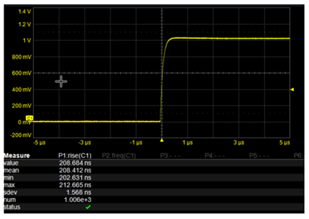
Figure 2: The Cal signal is a nominal 1-V pk-pk square wave
Now, say we remove that 3' length of coax and replace it with a 6' length. We would expect to now see a longer rise time, right? And in measuring it, indeed, the average rise time with the 6' cable has increased to about 370 ns. Why is this happening? One might presume that there's an RC charging effect going on in the cable, or perhaps unusually large signal losses, and if that's true, what if I wanted to use this cable to measure a fast-rising edge? It seems that I'd need an extremely short run of cable to do so. What's really going on here?
Essential Principles
To understand our Cal signal's variable rise times, we first want to cover some principles on which to base our thinking about transmission lines. The first of these is about thinking in the time and frequency domains and the connection between the two.
A signal represented in the time domain, such as an ideal square wave with a rise time = 0 ps (Figure 3), for instance, can be represented in the frequency domain. In translating from the former to the latter, we break the signal down into its frequency components. If the signal is of a repetitive nature in the time domain, as a square wave is, and has a period (T) associated with it, then 1/T = frequency, and the frequency components are multiples of the first harmonic. If it also happens that the waveform is anti-symmetric, which is to say that the first half of a cycle is the opposite of the second half, then the even harmonics have zero amplitude, so we have only odd-numbered harmonics.
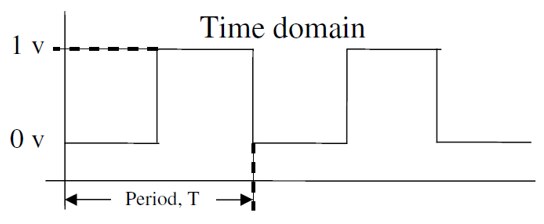
Figure 3: An ideal square wave shown in a time-domain representation
Looking at the same signal represented in the frequency domain (Figure 4), we note that the harmonics drop off in a well-defined pattern: Amplitude (A) = 2/πn, where n is the number of the harmonic.
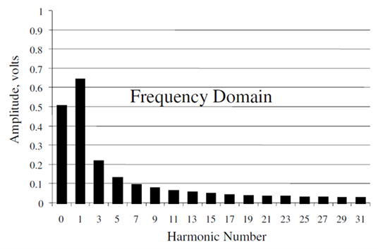
Figure 4: An ideal square wave shown in the frequency domain
How do these two domains connect? We can take this frequency spectrum, each of these frequency components being sine waves, and we can recreate, or synthesize, our ideal square wave in the time domain by summing all of these frequency components. Were we to add only, say, the first three harmonics (up to and including the fifth) and ignored the rest, we would be defining the highest frequency component in our spectrum. But we could go on to add the 7th, 9th, 11th, and so on, and in doing so, we would be impacting the rise time of our synthesized square wave.
Figure 5 shows us that impact; the straight plot is the fundamental frequency and 1st harmonic with the rest being higher harmonics. As we add more harmonics, or higher frequency components, the highest of those frequency components can be termed the signal's bandwidth, or, more precisely in this case, the engineered bandwidth. Adding harmonics increases the bandwidth until we reach about the 17th harmonic, above which there's little of significance left in terms of amplitude.
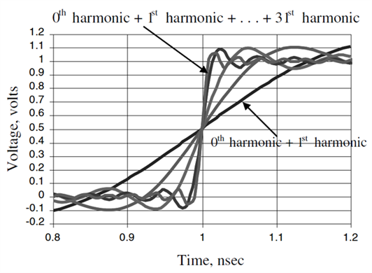
Figure 5: Rebuilding an ideal square wave from its frequency components
If we plot bandwidth vs. 10-90% rise time for these frequency components, we'll see that they fit into another well-defined pattern. The bandwidth is the inverse of the rise time, and it turns out that the bandwidth = 0.35/10-90% rise time. The graph in Figure 6 clearly shows the relationship between bandwidth and rise time, and this is the basis of that rule of thumb connecting the rise time of a signal and its highest frequency component. Thus, if you decrease the rise time, you increase the bandwidth, and vice versa.
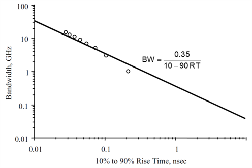
Figure 6: A plot shows the relationship between bandwidth and rise time
We'll continue this discussion of the underlying principles behind transmission lines in subsequent posts.