


Introduction
As many of you may know, there was a road test for the Particle.io WiFi / Thread Mesh kit back in August/September 2019. I was one of the road test reviewers and I really liked this mesh development kit.
So when Particle.io announced that they would be discontinuing Particle Mesh and that they would no longer be making the Xenon board, I was left wondering what I could do with the Particle Xenon board as I liked this board too (being a nRF52840 in a Feather form factor).
The Particle.io website suggested a number of alternatives for the Xenon board, including:
- Xenons can be reprogrammed to run CircuitPython in standalone (no network) mode; and
- Xenons can be reprogrammed to be a standard nRF52840 board using the nRD52 SDK. It can use a native Thread Mesh network in this mode, but will lose all Particle functionality.
As I was unfamiliar with either of those options and it seemed to me that the learning curve to get going with those options was also quite steep, I sadly shelved my Xenon board until I found an easier alternative.
Then in June 2020, I spotted an announcement from MBED that version 1.0 of Mbed Studio had just been released and that this was available for download on Linux OS.
I was curious to see what this IDE could do, so I went ahead and installed this IDE on my computer from the MBED Studio web page. This installation process also installs the MBED CLI and a bunch of other testing tools (e.g. MBED Greentea), which may come in handy at a later stage.
Let’s get started with MBED Studio
MBED Studio is based on the Eclipse Theia IDE, which according to the Theia website, embraces many of the design decisions and even directly supports VS Code extensions. Hence, the IDE looks remarkably similar to Microsoft’s Visual Studio Code, which is not surprising considering that also both are use the Monaco Editor.
For those familiar with Visual Studio Code, you'll get a similar user experience when launching MBED Studio.
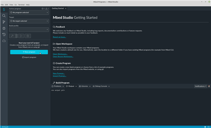
When you launch MBED Studio you are presented with a Getting Started page. This page provides options to open a workspace and to create a program. It also allows you to report an issue, although I found that this requires an SMTP server etc.
My natural instinct was to gravitate towards the message “Start your next IoT project” on the left hand pane and click on the large “+ New program” button beneath. This opens up a “New program” dialogue box which allows you to select an example program and give your program a name.
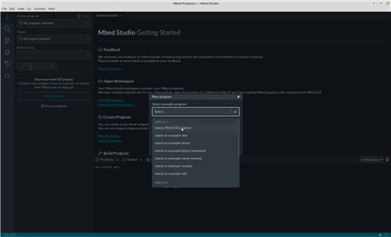
As you can see, you are presented with a small selection of example programs for either MBED OS 6 or for MBED OS 5.
My immediate thought was that this must be legacy related. It is also worth noting that the IDE does not prevent updates, because if you go and select an MBED OS 5 example it will use mbed-os 5.15.4 but then the IDE will still notify you to update the MBED OS to the latest version, which at the time of writing this is OS version 6.2.0. So beware, you’ll soon learn the reason why you are given the two options and also to not automatically update all MBED 5.x examples to MBED 6.x. One key reason is that external libraries created using MBED OS 5.x will seldom work on MBED OS 6.x. More on this later.
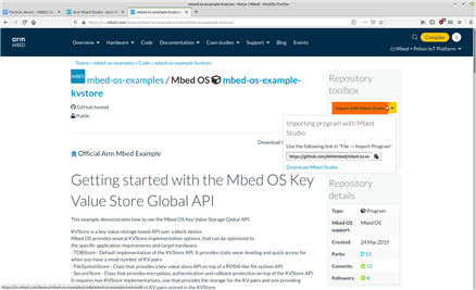
Another first impression I had was that I felt that the 7 “official” examples listed for MBED OS-6 / OS-5 was rather limiting. Not to worry, as I soon discovered that if you head over to the Code page on MBED website you can use any of the official or user-contributed examples listed there too (although you need to be mindful that not all MBED compatible hardware works seamlessly on MBED Studio - remember, it’s only version 1.0 and that most libraries found listed here are for MBED OS 5 or even MBED OS 2).
If you head over to the MBED Code Page you can choose a program, such as one of the official examples, and then on the right hand side of the page there is an option under “Repository toolbox” to create a link to import the program into MBED Studio. For more details, it is well worth reviewing the MBED documentation. For example, here is a link that explains how to create and import a program.
Let’s now start with the proverbial “Hello World” example (mbed-os-example-blinky) using the latest MBED OS 6.2.0.

If you open up main.cpp, you may be like me and be rather surprised to see code syntax errors. The reason you get this is that no “Target” has been selected. This is very similar behaviour to the online compiler, which links your example to hardware.
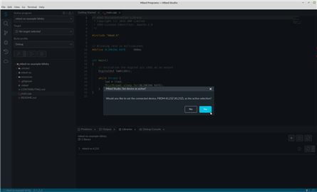
I discovered by accident a quick way to choose your target. Simply plug the board in and if it has a compatible debug/flash/bootloader interface it will automatically be detected.
As I was just learning, I started with an MBED board I was familiar with, namely a FRDM-KL25ZFRDM-KL25Z board. My FRDM-KL25ZFRDM-KL25Z board is a good few years old but it still works. Here you plug the USB cable into the OpenSDA port and after a good couple of seconds a message pops up on the screen as you if you want to set the device detected as active. Clicking “Yes” selects the target for you. Now you will find all those code syntax errors have been resolved.
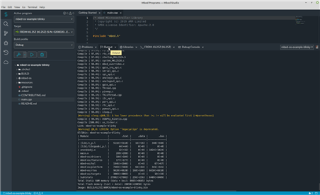
We are now ready to compile or build our program. To do that we select the hammer icon on the left hand side of your screen (below the Build Profile selection option). The first compile does take awhile (a couple of minutes depending on the speed of your computer) but you are provided with a running update on the output console.
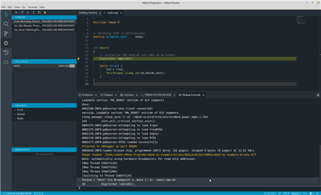
We now have two options. Either “run” or “debug” your program. If we select the “debug” option we are now presented with a helpful debug screen:
But as this is such a straightforward program, the run option is all you need to see the blinking LED. Here's a video capturing the whole start to finish process:
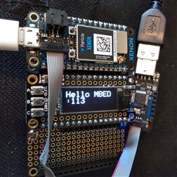
Let me now do the same for my Particle.io Xenon board.
As you can see it is pretty straightforward to get started.
Let's now broaden our horizons.
Moving beyond “blinky”
First, a word of caution before you head off and create loads of new programs in MBED Studio. I found that version 1.1 of the IDE still has a few teething problems. For example, with the Linux version it will only list two program examples on the left hand pane (and there is a work around available - just search on the MBED forum for the solution). Another example is when trying to select the content from the MBED Studio serial output, it does not highlight, using a different background colour, which content you have selected. So you think the copy and paste option does not work. All these little issues have been raised and will no doubt be addressed soon enough.
Besides using a developing IDE, the biggest challenge you’ll have to date is getting some of the many user-contributed examples to work with MBED OS 6.x as currently most are written using MBED OS 5.x or even MBED OS 2. The good news is that MBED 6.x has a bare metal profile to cater for OS 2 and the standard thread based profile for new and OS5 type examples.
The website does document the deprecated API's, which will help you when moving from MBED OS 5.x to OS 6.x (in most cases you usually just get a warning if still used).
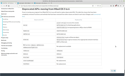
I also noticed that MBED OS 6.x changes go beyond just deprecated functions. From what I can make out there are plenty of breaking changes to the functions themselves. Here is one example for the “InterruptIn” class. In this case if an OS 5.x example uses the “InterruptIn” class then this will cause an error if trying to port across to OS 6.x. Here is Version 5.14 and here is Version 6.2.
Despite these changes, from what I’ve noticed (although I am certainly no expert) things look much neater with MBED OS 6 than MBED OS5 and confirms to me that MBED really is maturing into something really good.
Let's now delve into some examples.
Digital IO
Our Xenon (or Feather form factor) board was never built for MBED, so the pin names shown on the board’s screen print will not be understood by the MBED OS, which thinks we are using a nRF52840 DVK. So, we’ll need to look at the Xenon schematic and/or a pinout diagram to map all GPIO’s.
| {gallery:autoplay=false} Xenon Schematic |
|---|
|
|


A review of the schematic, or block diagram, will confirm that the Analog pins match those in MBED, but the digital pins differ. So, in order to use the digital pins correctly we will need to define our own pin mappings in our code.
To demonstrate that our pin mappings work, here’s a simple program sketch, which uses two digital inputs (for momentary button switches) and four digital outputs (for LED’s). The sketch also highlights two different flow control methods, which are available with MBED.
/* mbed Microcontroller Library
 * Digital IO example
 * Copyright (c) 2020 Gerrikoio (BigG)
 * SPDX-License-Identifier: Apache-2.0
 */

#include "mbed.h"
#include "mbed_events.h"

// Xenon Pin Map - Digital Pins differ
// Xenon Pin Map - the Analog pins match up
#define XEN_D2      p33
#define XEN_D3      p34
#define XEN_D4      p40
#define XEN_D5      p42
#define XEN_D6      p43
#define XEN_D7      p44
#define XEN_D8      p35

// The Xenon RGB LED is matched to default LED pin names.
DigitalOut red_led(LED1, 1);
DigitalOut green_led(LED2, 1);
DigitalOut blue_led(LED3, 1);

// The Xenon Mode button is matched to BUTTON1
DigitalIn mode_btn(BUTTON1, PullUp);

// We create our own user LED and Button
DigitalOut user_led(XEN_D4, 0);
DigitalIn user_btn(XEN_D5);

uint8_t RGBcolour = 1;              // This is used to determine which RGB LED is on
bool modeClick = false;

// We will use a "ticker" for handling RGB LED blinking
Ticker ticker;

void blink() {
    if (RGBcolour == 1) red_led = !red_led;
    else if (RGBcolour == 2) green_led = !green_led;
    else if (RGBcolour == 3) blue_led = !blue_led;
}

// A wrapper function that attaches the ticker to a timer interrupt
void start_blinking() {
    ticker.attach(blink, 500ms);                // we define a 500ms blinking rate
}

int main()
{
    if (mode_btn.read()) start_blinking();      // If mode button is pressed on power up then no RGB LED's
    while (true) {
        // We use the polling method to read button states and handle the user LED on/off state
        if (!mode_btn.read()) {
            if (!modeClick) {
                modeClick = true;
                red_led = 1;
                green_led = 1;
                blue_led = 1;
                if (RGBcolour < 3) RGBcolour++;
                else RGBcolour = 1;
            }
        }
        else {
            if (modeClick) modeClick = false;
        }

        if (user_btn.read())  user_led = 1;
        else  user_led = 0;
    }
}
The second digital IO example is a little fancier, uses an ultrasonic sensor and a 4-digit display. The example also includes the use of the onboard RGB LED (used to indicate distance range) and demonstrates how to setup and use a virtual serial port, which you need to create if you want serial IO via USB.
In this example a SeeedStudio Grove ultrasonic sensor is used, which only uses one digital pin as both an input and an output. With the 4-digit display I am using a user-contributed library imported from the MBED website. Thankfully in this case the library worked without issue.
/* mbed Microcontroller Library
 * Digital IO example using Grove Ultrasonic Sensor and 4-digit display
 * A virtual serial port is also used
 * Copyright (c) 2020 Gerrikoio (BigG)
 * SPDX-License-Identifier: Apache-2.0
 */

#include "mbed.h"

// We need to set up a virtual com port to see serial output via USB
#include "USBSerial.h"

// Using the Seeed Grove 4-digit display library
#include "DigitDisplay.h"

// Set up virtual serial port over USB for the Particle Xenon (using original vendor/product id's)
USBSerial serial(true, 0x2b04, 0xc00e);

// Xenon Pin Map - Digital Pins differ
// Xenon Pin Map - the Analog pins match up

#define XEN_D2      p33
#define XEN_D3      p34
#define XEN_D4      p40
#define XEN_D5      p42
#define XEN_D6      p43
#define XEN_D7      p44
#define XEN_D8      p35

EventQueue queue;

DigitalOut Red_led(LED1,1);
DigitalOut Green_led(LED2,1);
DigitalOut Blue_led(LED3,1);

DigitalInOut GroveTrig(XEN_D2);

DigitDisplay FourDigit(XEN_D4, XEN_D5); // P1/P15

Timer Pulsetimer;

static uint32_t MicrosDiff(uint32_t begin, uint32_t end)
{
    return end - begin;
}

static uint32_t pulseIn(uint32_t timeout = 1000000L)
{
    Pulsetimer.start();

    uint32_t begin = Pulsetimer.elapsed_time().count();

    // wait for any previous pulse to end
    while (GroveTrig.read()) if (MicrosDiff(begin, Pulsetimer.elapsed_time().count()) >= timeout) return 0;

    // wait for the pulse to start
    while (!GroveTrig.read()) if (MicrosDiff(begin, Pulsetimer.elapsed_time().count()) >= timeout) return 0;
    uint32_t pulseBegin = Pulsetimer.elapsed_time().count();

    // wait for the pulse to stop
    while (GroveTrig.read()) if (MicrosDiff(begin, Pulsetimer.elapsed_time().count()) >= timeout) return 0;

    uint32_t pulseEnd = Pulsetimer.elapsed_time().count();

    Pulsetimer.stop();

    return MicrosDiff(pulseBegin, pulseEnd);
}

void MeasureDistInCentimeters(void)
{
    GroveTrig.output();  // attach the address of the flip function to the rising edge
    GroveTrig.write(0);
    wait_us(2);
    GroveTrig.write(1);
    wait_us(5);
    GroveTrig.write(0);

    GroveTrig.input();  // attach the address of the flip function to the rising edge

    long duration = pulseIn();
    long RangeInCentimeters = duration/29/2;

    serial.printf("Dist: %lucm\r\n", RangeInCentimeters);
    FourDigit.write((int16_t)RangeInCentimeters);

    // Use LED's to show distance measured
    if (RangeInCentimeters > 100) {
        Red_led = 1;
        Green_led = 1;
        Blue_led = 0;
    }
    else if (RangeInCentimeters > 40) {
        Red_led = 1;
        Green_led = 0;
        Blue_led = 1;
    }
    else {
        Red_led = 0;
        Green_led = 1;
        Blue_led = 1;
    }
}


int main()
{

    FourDigit.on();

    queue.call_every(1s, MeasureDistInCentimeters);
    queue.dispatch_forever();

}
Analog IO's
Here’s another simple sketch, which plays around with two analog inputs and uses the values to produce a PWM output. Here I am using an analog light sensor and a potentiometer as inputs and I’ve attached a piezo buzzer to a PWM output. No doubt the code could be improved upon to make a less annoying audio output.
/* mbed Microcontroller Library
 * Analog IO example
 * Copyright (c) 2020 Gerrikoio (BigG)
 * SPDX-License-Identifier: Apache-2.0
 */

#include <mbed.h>

// Xenon Pin Map - Digital Pins differ
// Xenon Pin Map - the Analog pins match up
#define XEN_D2      p33
#define XEN_D3      p34
#define XEN_D4      p40
#define XEN_D5      p42
#define XEN_D6      p43
#define XEN_D7      p44
#define XEN_D8      p35

DigitalIn   Button(A1);
AnalogIn    LightSensor(A2);
AnalogIn    Potientometer(A0);
PwmOut      spkr(XEN_D4);

const float FREQMID = 3500.0;                       // initialising the high frequency range
const float FREQPERIOD = 1.0;                       // initialising the output tone
const long TONELENGTH = 350000;                     // initialising the time each tone will hold


int main()
{
    float f_change = 0.0;
    float p_vol = 0.0;

    while (true) {
        if (Button.read()) {

            f_change = FREQMID - ((LightSensor.read() - 0.5) * 2000.0);
            p_vol = Potientometer.read() * 0.6;           // output volume -- my buzzer doesn't like full vol

            spkr.period(FREQPERIOD/f_change);       // PWM output frequency
            spkr.write(p_vol);                      // output volume
        }
        else {
            spkr.period(0);                         // PWM output frequency
            spkr.write(0);                          // output volume
        }
        wait_us(TONELENGTH);                        // length of each tone

    }
}
OLED display via I2C bus
In this 4th and final example, I am demonstrating the use of the I2C bus with a Featherwing OLED display. This is another library port but this time I did have to make a few minor adjustments to get it to work properly.
/* mbed Microcontroller Library
 * SSD1306 OLED Display example using I2C bus
 * Libraries obtained via MBED.com (Code page)
 * Copyright (c) 2020 Gerrikoio (BigG)
 * SPDX-License-Identifier: Apache-2.0
 */

#include <mbed.h>
#include "USBSerial.h"
#include "Adafruit_SSD1306.h"//include the adafruit library for the oled display

EventQueue queue;

I2C i2c(I2C_SDA0, I2C_SCL0);

// Set up virtual serial port over USB for the Particle Xenon (using original vendor/product id's)
USBSerial serial(true, 0x2b04, 0xc00e);

Adafruit_SSD1306_I2c oled(i2c,0x78); //0111 1000

void OLEDdisplay_Handler(void)
{
    static uint32_t xx=0;
    char displayText[32] = {'\0'};
    sprintf(displayText, "Hello MBED:%u", xx);
    oled.clearDisplay();
    oled.display();
    oled.clearDisplay();
    oled.setTextSize(2);
    oled.setTextCursor(0,0);
    oled.printf("%s", displayText);
    oled.display();
    serial.printf("%s\r\n", displayText);
    xx++;
}


int main()
{
    oled.setRotation(2);
    queue.call_every(1s, OLEDdisplay_Handler);
    queue.dispatch_forever();

}
Video demo of examples
Using the MBED BLE API with nRF52840 (Xenon boards)
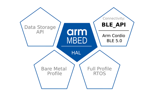
Finally, we get the interesting part where we use the MBED BLE API with our Xenon boards.
If you're a C++ expert and have a good grasp of the BLE stack, you will probably feel comfortable with the code and have no problems understanding the logic to make changes. I, on the other hand, have a long way to go and this was a big stretch for me to understand how they’ve constructed the classes, used templated classes, and then how the callback functions were created and linked together etc.
So apologies in advance if I have got parts wrong, as to be honest, I’m a little out of my depth here when it comes to trying to explain the MBED BLE API in detail. So here goes a cursory overview of how the BLE API works, using an example I created.

My example is based on the MBED BLE_Button example, which is available for both MBED OS 5 and MBED OS 6.
The BLE_Button readme file describes this example as a "BLE service template, which handles a read-only or notify type characteristic. The characteristic’s value gets its boolean state depending on whether the onboard button it’s pressed or released".
As this simple BLE peripheral example used a custom 16-bit UUID rather than a 128-bit UUID for both the button GATT service and it’s associated characteristic, I decided to modify and use the standardised Automation IO Gatt Service (0x1815) instead, for the same purpose. So, instead of the custom characteristic, my example uses the standardised Digital IO characteristic (0x2A56) to give me the button toggle binary status.
I also decided to enhance the application’s capability by adding two more characteristics for digital IO’s - one for another button (input) and another for an LED (output).
Anyhow, before jumping into the code I need to introduce a new file, which was optional beforehand but it’s needed here, namely mbed_app.json. I am not going to attempt to explain what can or cannot be included in this file. For that, I suggest you start with this link. I'll start with the category "target_overrides" as shown here:
   "target_overrides": {
        "K64F": {
            "target.components_add": ["BlueNRG_MS"],
            "target.features_add": ["BLE"],
            "target.extra_labels_add": ["CORDIO"],
            "ble_button_pin_name": "SW2"
        },
        "NUCLEO_F401RE": {
            "target.components_add": ["BlueNRG_MS"],
            "target.features_add": ["BLE"],
            "target.extra_labels_add": ["CORDIO"]
        },
        "NUCLEO_WB55RG": {
            "ble_button_pin_pull": "PullUp"
        },
        "NRF52840_DK": {
            "target.features_add": ["BLE"],
            "ble_button_pin_pull": "PullUp"
        },
        "NRF52_DK": {
            "target.features_add": ["BLE"]
        },
        "EP_AGORA": {
            "ble_button_pin_name": "PIN_NAME_PUSH_BUTTON",
            "target.macros_add":   ["NRFX_GPIOTE_CONFIG_NUM_OF_LOW_POWER_EVENTS=4"]
        }
    }
The two expressions worth noting are “target.features_add”, which adds in the BLE feature, and “target.extra_labels_add” which links in the Cordio BLE stack if it’s required for the module to work. For the Xenon board all we need is the "target.features_add": ["BLE"] property.
If you want to delve a little deeper into what makes up the “NRF52840_DK” target on MBED, you'll need to look within the MBED OS directory in your example application on MBED Studio.
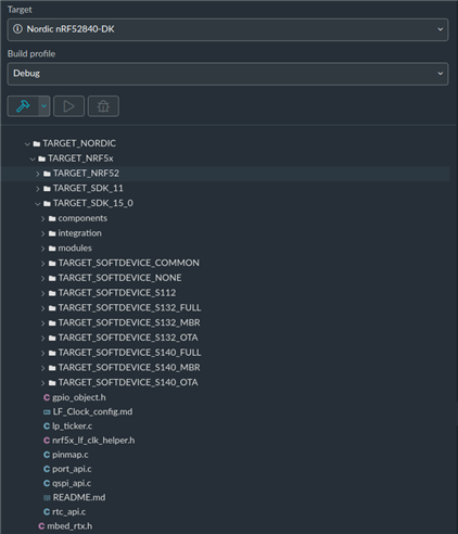
Here we can see that the “TARGET_NORDIC” includes the Nordic Semiconductor’s SDK 15 and the relevant “SOFT_DEVICE” bootloader packages.
There is also a README.md file within the TARGET_NORDIC/TARGET_NRF5x folder that provides further explanation on further refinements you can, if needed.
For me, I stuck with the defaults and they seem to work fine.
Peripheral Example
The mbed_app.json file also allows you to predefine your own pin names instead of creating #define’s in your code. For this you create a config section.
So here I created a config for my Xenon board (I realise what I’ve done applies to all boards but as this is just a demo, it will suffice). Here I have define a pin name for the GPIO attached to my LED (p33) and a pin name for the GPIO attached to my 2nd button.
To review the details and the code for the Peripheral device, these can be found on my Github repository: https://github.com/Gerriko/mbedos6_blePeripheral_AutomationIO
Let's review the code structure.
The peripheral example is made up of 3 files, which are all placed in an optional “source” folder, namely
- DigitalIO.h
- main.cpp
- pretty_printer.h
The DigitalIO.h defines a class “DigitalIOService”, which essentially defines our Automation IO Gatt Service and it’s behaviour.
This follows the same structure as defined in the Mbed BLE_Button example, which has a “ButtonService” class defined in the ButtonService.h file.
Note, that all the MBED BLE examples for MBED OS 6 are available on their GitHub repository: https://github.com/ARMmbed/mbed-os-example-ble
Within my class “DigitalIOService”, I’ve also included a 0x2901 User Defined descriptor for each of my characteristics. This is a nice enhancement worked out by yours truly (fist pump).
Within main.cpp we have another class called “DigitalIOdemo”. This class handles both the BLE and the button trigger (interrupt) events. We also use this class to declare our GPIO’s.
Finally we have “pretty_printer.h”. This handles printing out the BLE error codes on the serial terminal. As the Xenon board uses a virtual serial terminal I included the “USBSerial.h” file here and created the USBSerial instance for printf.
Central Example
Setting up a central device was some challenge.
The closest example available on the MBED Github repository is the BLE_LEDBlinker example and as you will see in my code, I used the same class name and file structure.
This example shows how to scan for peripheral devices. Unfortunately, it only scans for a BLE local name, which some might argue is not considered best practice. So I had to investigate how to search out for a UUID instead.
This is all handled within a function called “onAdvertisingReport” where within this function you parse out the advertising payload and you can then check what the “field.type” contains.
The BLE_LEDBlinker central client example was also designed to work with the BLE_LED peripheral example, which uses one characteristic with READ and WRITE attributes. But as my peripheral device uses NOTIFY, I needed to work out how to enable the notifications.
After some searching, I found that the MBED BLE_GattClient example had a method to enable notifications. However, this example demonstrates the unusual case of having a peripheral device acting as a client and the central device (i.e. a phone) acting as a server. Also the way this example was structured and coded made it quite difficult to follow the logic. After some very painstaking perseverance I eventually got it all working.
Here are a few insights.
The next important event after the “onAdvertisingReport” is the connection event and this is handled by the "onConnectionComplete" function. Within this function we set up the important callback functions for different BLE stack processes. The first is the "launchServiceDiscovery" process and the other is the "onServiceDiscoveryTermination" process. We also need to set up two event callbacks. The first is for the NOTIFY event which is handled by this function "onHVX" and the second is a WRITE event handler via the "onDataWritten" function. I discovered through much trial and error that the "onDataWritten" function is rather important for handling the CCCD write request and for processing the next "discovery descriptor" process.
The "launchServiceDiscovery" process is where the service and characteristics details are handled. Here we need to save the characteristic details as we need those for later. Then when the "onServiceDiscoveryTermination" event fires we can start with our Descriptor discovery process, which is handled by the "discoverDescriptors" process.
As you can see there is quite a bit to get your head around but once you do, it will make sense.
The code for the central example can be found here: https://github.com/Gerriko/mbedos6_bleCentral_AutomationIO
Other Examples
I have now tested all the BLE examples available in the MBED Github repository and they all work. It does take awhile to get to grips with the code as there are no tutorials available. All you have brief supporting documentation on mbed.com and the example code. Thus you find yourself having to trawl through the code itself, which actually is well commented, to make sense of the logic.
So now that I’ve earned my Mbed BLE_API stripes using the Xenon boards, I hope to get creative and explore other ideas and boards too as I can now see that Mbed OS 6.2 and Mbed Studio have great potential for embedded IoT devices.
This journey will no doubt be continued...

