element14 Community
element14 Community
    Register Log In
  • Site
  • Search
  • Log In Register
  • Community Hub
    Community Hub
    • What's New on element14
    • Feedback and Support
    • Benefits of Membership
    • Personal Blogs
    • Members Area
    • Achievement Levels
  • Learn
    Learn
    • Ask an Expert
    • eBooks
    • element14 presents
    • Learning Center
    • Tech Spotlight
    • STEM Academy
    • Webinars, Training and Events
    • Learning Groups
  • Technologies
    Technologies
    • 3D Printing
    • FPGA
    • Industrial Automation
    • Internet of Things
    • Power & Energy
    • Sensors
    • Technology Groups
  • Challenges & Projects
    Challenges & Projects
    • Design Challenges
    • element14 presents Projects
    • Project14
    • Arduino Projects
    • Raspberry Pi Projects
    • Project Groups
  • Products
    Products
    • Arduino
    • Avnet Boards Community
    • Dev Tools
    • Manufacturers
    • Multicomp Pro
    • Product Groups
    • Raspberry Pi
    • RoadTests & Reviews
  • About Us
  • Store
    Store
    • Visit Your Store
    • Choose another store...
      • Europe
      •  Austria (German)
      •  Belgium (Dutch, French)
      •  Bulgaria (Bulgarian)
      •  Czech Republic (Czech)
      •  Denmark (Danish)
      •  Estonia (Estonian)
      •  Finland (Finnish)
      •  France (French)
      •  Germany (German)
      •  Hungary (Hungarian)
      •  Ireland
      •  Israel
      •  Italy (Italian)
      •  Latvia (Latvian)
      •  
      •  Lithuania (Lithuanian)
      •  Netherlands (Dutch)
      •  Norway (Norwegian)
      •  Poland (Polish)
      •  Portugal (Portuguese)
      •  Romania (Romanian)
      •  Russia (Russian)
      •  Slovakia (Slovak)
      •  Slovenia (Slovenian)
      •  Spain (Spanish)
      •  Sweden (Swedish)
      •  Switzerland(German, French)
      •  Turkey (Turkish)
      •  United Kingdom
      • Asia Pacific
      •  Australia
      •  China
      •  Hong Kong
      •  India
      •  Korea (Korean)
      •  Malaysia
      •  New Zealand
      •  Philippines
      •  Singapore
      •  Taiwan
      •  Thailand (Thai)
      • Americas
      •  Brazil (Portuguese)
      •  Canada
      •  Mexico (Spanish)
      •  United States
      Can't find the country/region you're looking for? Visit our export site or find a local distributor.
  • Translate
  • Profile
  • Settings
Personal Blogs
  • Community Hub
  • More
Personal Blogs
Legacy Personal Blogs Using the Fixed Voltage Reference (FVR) module for a precise A/D conversion in enhanced mid-range 8-bit PIC microcontrollers
  • Blog
  • Documents
  • Mentions
  • Sub-Groups
  • Tags
  • More
  • Cancel
  • New
  • Share
  • More
  • Cancel
Group Actions
  • Group RSS
  • More
  • Cancel
Engagement
  • Author Author: Former Member
  • Date Created: 20 Dec 2011 3:33 PM Date Created
  • Views 1663 views
  • Likes 0 likes
  • Comments 0 comments
  • a/d_conversion
  • pic16f1827
  • microchip
  • fvr_module
  • pic_microcontrollers
Related
Recommended

Using the Fixed Voltage Reference (FVR) module for a precise A/D conversion in enhanced mid-range 8-bit PIC microcontrollers

Former Member
Former Member
20 Dec 2011

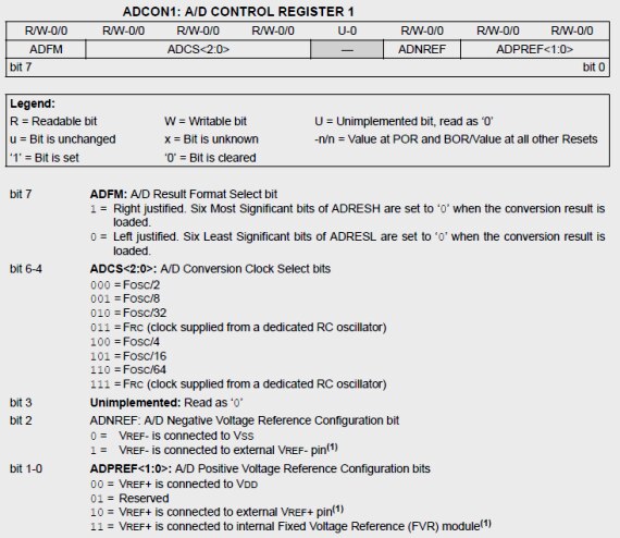
A reference voltage plays a vital role in determining the range and the resolution (Volt/Count) of an A/D conversion. Besides, the absolute accuracy and the precision of the conversion also depend upon how accurate and stable the reference voltage is. Usually in PIC microcontrollers, the reference voltage for A/D conversion can be selected as the supply voltage (VDD) itself or provided externally through one or more I/O pins. The supply voltage may not be a good choice for the reference voltage where a precise A/D conversion is required unless you are confident that the supply voltage is very stable. Otherwise you need an external source of reference voltage, which will increases the hardware cost of your design and also consume a few of your I/O resources. Microchip's latest enhanced mid-range family of 8-bit PIC microcontrollers feature the Fixed Voltage Reference (FVR) module to generate a reference voltage internally. The output of the FVR module is stable and less susceptible to any fluctuations in the supply voltage. The FVR module can be configured to use its output as a reference voltage for A/D conversion internally, thus reducing the cost and freeing up one or more I/O pins.


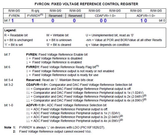
In order to continue this discussion further I am selecting PIC16F1827-E/P.PIC16F1827-E/P., which is a member of Microchip’s enhanced mid-range 8-bit  microcontroller family. It is pin-compatible with the popular 18-pin  predecessors such as PIC16F628A and PIC16F88, but is equipped with lot  more peripherals and other features. The Fixed Voltage Reference (FVR)  module in PIC16F1827 provides three software selectable voltage levels,  1.024 V, 2.048 V and 4.096 V. The output can be configured to supply a  reference voltage to the following:


• ADC input channel
• ADC positive reference
• Comparator positive input
• Digital-to-Analog Converter (DAC)
• Capacitive Sensing (CPS) module


Why the reference voltages are non integers like 1.024, 2.048, or 4.096 V?   


The reference voltage of 1.024, 2.048, or 4.096 V  makes calculations easier and accurate in A/D conversion. For example,  if the positive A/D reference is 2.048 V and the negative reference is 0  V, then the resolution of 10-bit A/D conversion is 2.048 V/ 1024 = 2  mV/Count, which means in order to get the analog value (in mV) back from  the digital count, you just need to multiply the count by 2. Similarly,  the positive reference voltage of 4.096 V gives the conversion  resolution of 4 mV/Count.


The FVR output voltage is actually 1.024 V, but with the  help of programmable gain amplifiers, it is amplified by 1x (1.024  V), 2x (2.048 V), or 4x (4.096 V), to produce the three possible voltage  levels. The FVRCON register (shown below) is used to configure the settings for the fixed voltage reference. The individual bit values of FVRCON  register to generate 2.048 V as the positive voltage reference for A/D conversion are shown below in blue color font.
image
Once the FVRCON register is configured, the choice of reference voltage for A/D conversion is made through ADCON1 control register (shown below). By setting  ADPREF<1:0> bits to ’1′, the positive reference voltage for A/D  conversion is derived from the internal FVR module. Clearing the ADNREF  bit connects the A/D negative reference voltage pin to the ground (VSS).
image
Now the reference voltage is set to the FVR output, the rest of the A/D conversion process is similar to any other PIC microcontroller.


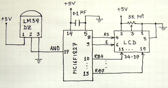
In the following link I have described the full software implementation of FVR module in A/D conversion for reading the analog output from an LM34 temperature sensor. I hope you will find it useful.


http://embedded-lab.com/blog/?p=3045


image

  • Sign in to reply
element14 Community

element14 is the first online community specifically for engineers. Connect with your peers and get expert answers to your questions.

  • Members
  • Learn
  • Technologies
  • Challenges & Projects
  • Products
  • Store
  • About Us
  • Feedback & Support
  • FAQs
  • Terms of Use
  • Privacy Policy
  • Legal and Copyright Notices
  • Sitemap
  • Cookies

An Avnet Company © 2025 Premier Farnell Limited. All Rights Reserved.

Premier Farnell Ltd, registered in England and Wales (no 00876412), registered office: Farnell House, Forge Lane, Leeds LS12 2NE.

ICP 备案号 10220084.

Follow element14

  • X
  • Facebook
  • linkedin
  • YouTube