


Hi, I am a first time poster here, and I wanted to create a blog about a project that I have always wanted to do, but my life wandered off in a different direction for a while! I have always been fascinated with robots and electronics, and even studied it at college. Well, here I am 15 years later, finally getting round to it.. better late than never right?
enough of the life events, back to the project - My goal is to create an autonomous robot that runs on tracks and navigates around a room, it would be wireless and have a camera.
The First goal, basic component selection!
Tracked Chasis
Raspberry Pi 2
Pi Camera
Arduino
DC motors
IR object detection sensors
7.2v 3700mAh battery.
Compass Module for orientation
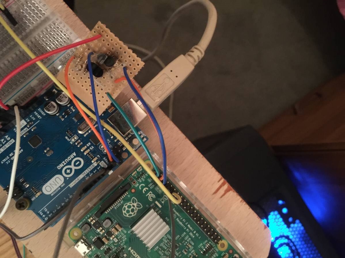
Stage 1: PI->Arduino Communication
I selected I2C as the communication protocol to get the 2 devices talking to each other. Before I could do this, I had to make myself a logic level converter, pretty simple enough with 4 NPN transistors and a few resistors. don't want to blow anything up just yet! Now I could have bought one of these pre-made, but what better to shake off the rust than to make myself make it! besides i needed the soldering practice.
I then moved on to coding. I wanted to get all communications modes working as reliably as I possibly could, I intend the Pi to be the brain, so it is important that this is rock solid.
I tried Wiring Pi, it had issues with communication errors, I then tried using the SM BUS directly myself which also had the same issues, and finally reverted to writing it completely using registers. The base issues were caused by the fact that the PI does not support clock stretching as documented, so once i worked that out and tweaked the Baud to prevent it - I was on a winner! I also had to write basic GPIO functions to enable the I2C functions on the shared output pins.
the good old internet was my friend here, and I used the Data sheet and also referenced the following page: www.peieter-jan.com/node/15
My code is available on Git and everyone is welcome to take a look at it https://github.com/wilkiePJ/BCM2835
its also available to clone from: https://github.com/wilkiePJ/BCM2835.git
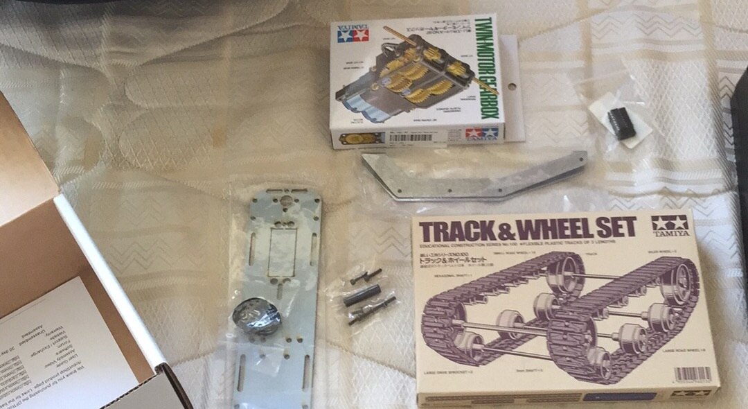
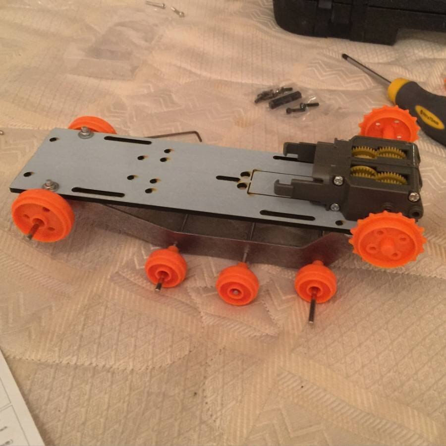
Stage 2: Build the chassis
Now, I could have moved on to more electronics protyping, as I still needed to build the DC motor driver board, but I wanted to break it up a bit, so I thought I would build the chassis.
It came in a useful kit which needed to be assembled:
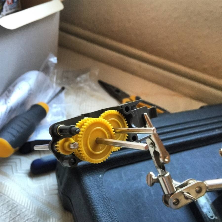
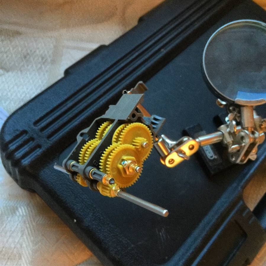
I decided to start with the gearbox:
And then onto the actual chassis
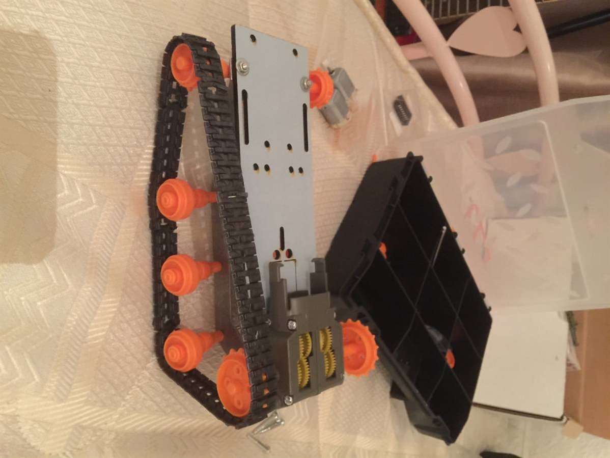
Now its was time to start playing with the sensors - at this point, its no more than a glorified arduino holder! or a printer decoration 
Stage 3: Build the Motor Driver
I needed a driver for my motors, I had 2 brushed 6v DC motors, and I needed them to go forwards and backwards, one for each track. This means I needed a H-Bridge IC. I decided on the 754410 Quad halfbridge chip, it had everything i needed so I moved on to prototyping.
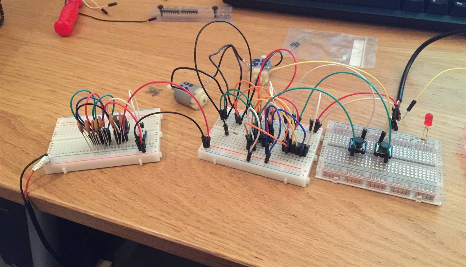
Once I knew I had it working - I soldered the board and then tested that it still worked of course I couldn't resist putting it to full power!
I then put it into the chassis to test them when driving the gearbox and the tracks, this was only at 30% power though - didn't want to wreck the tracks
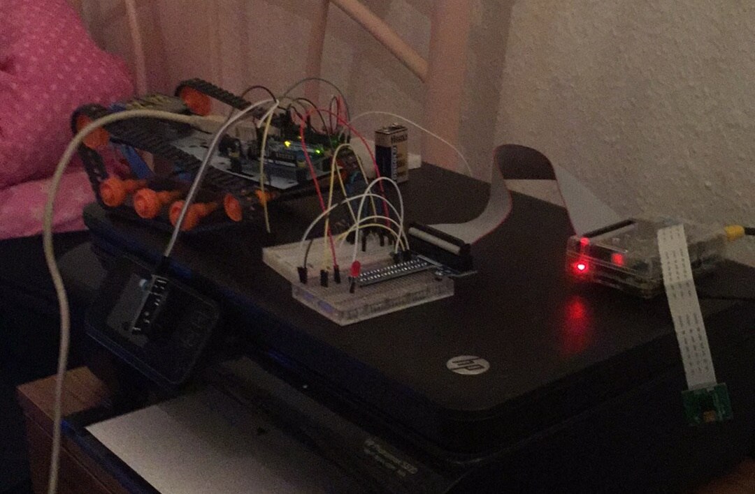
Stage 4: Test the full combination
Now I had motors, sensors, PI and arduino and I2c all working, it was time to test to see if the motors pulled the robot, and that the sensor cut out the motor when it saw an object. If this worked, I could start in making the power system more efficient by replacing the linear regulators with switching regulators and add the battery.
SUCCESS - Now to solve the power issues and add the camera and refine the sensor function and of course, the compass which I am really looking forward to using..... more to follow.....