


Working with an ABB robot
1. Introduction
Hi! As a part of one of my classes in university I had great opportunity to work with an ABB industrial robot arm for the end project. The class is about flexible automation and CNC machines, so I thoroughly enjoyed the class. As our finishing project for this class, we had to design and make a few pieces of a puzzle and fingers for a gripper where robot would then go and put the puzzle together. We had to design the 3D models and make the parts either on a 3D printer or a CNC mill. I got some cool videos out of this project, so I thought I would share that here. The puzzle had to have 3 pieces and had to meet some simple requirements, so in the end, my group designed this puzzle.
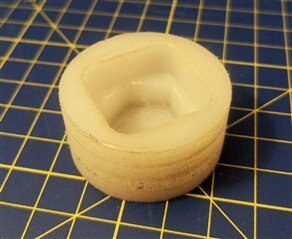
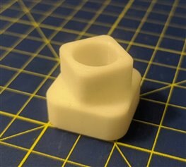

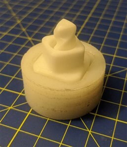
As you can see from the picture, the first part was made on the CNC mill, while the other 2 were made on a 3D printer. The goal was for the robot to assemble this, by first placing the base down which is on the first picture, then place the axle inside the base which is on the third picture and in the end the top over the axle and into the base. The assembled puzzle should look something like this:
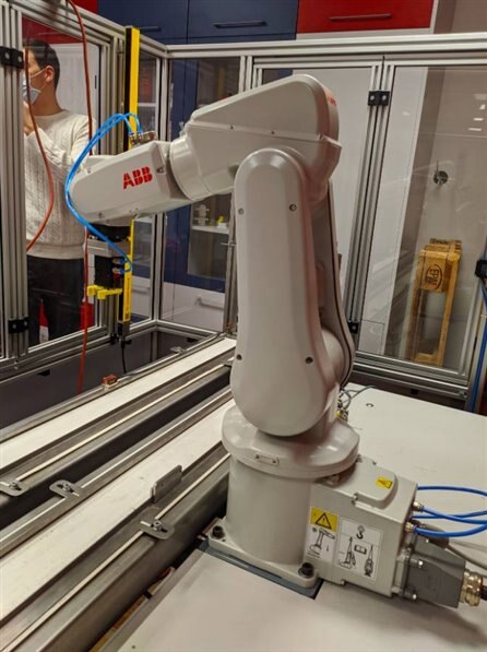
2. IRB 120
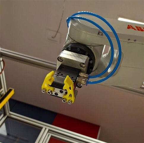
In the robotics laboratory we currently have 2 robot arms, one being a Denso robot arm, and the other one is the ABB robot arm which I worked with. The arm in question is an ABB IRB120-0.58m-3kg. It had an already attached gripper to it, a PQ2516. I made a 3D printed mock up of this gripper on my own to test out and make sure the gripper fingers we designed worked fine which I'll cover in another blog.

One thing that I love about this robot is the controller that can be seen on the second picture. It's an incredibly powerful tool for controlling the robot, but also extremely intuitive. I was over cautious of course in the beginning not wanting to damage the robot, but the controller became really easy to use after a few minutes. On the back on the controller (don't have pictures of that sorry), behind where the joystick is, there is a really cool safety feature. There is a safety switch that you need to hold for the robot to run, but, if you press the switch too hard, it shuts off the robot. The idea behind that, if someone gets muscle cramps from an electrical shock, the robot would shut down. I really found that an extremely genius feature of the controller.
3. Gripper
This was the most fun part to design since the pieces of the puzzle were more than simple. This was one of my tasks and I had a lot of fun with it at home, experimenting with various gripper finger designs. To grab the our puzzle pieces, we had to pick up the base from the inside, and the other 2 pieces from the outside. There are a few variations for the configuration that could be had with the gripper, with the easiest design being having a part of the gripper dedicated to every part. The more fun, but a bit more design challenging way would be to, to use one part of the fingers for all three pieces, which is what I did. It was an iterative process to get to a version that worked properly, so here are all of the different models that I made.
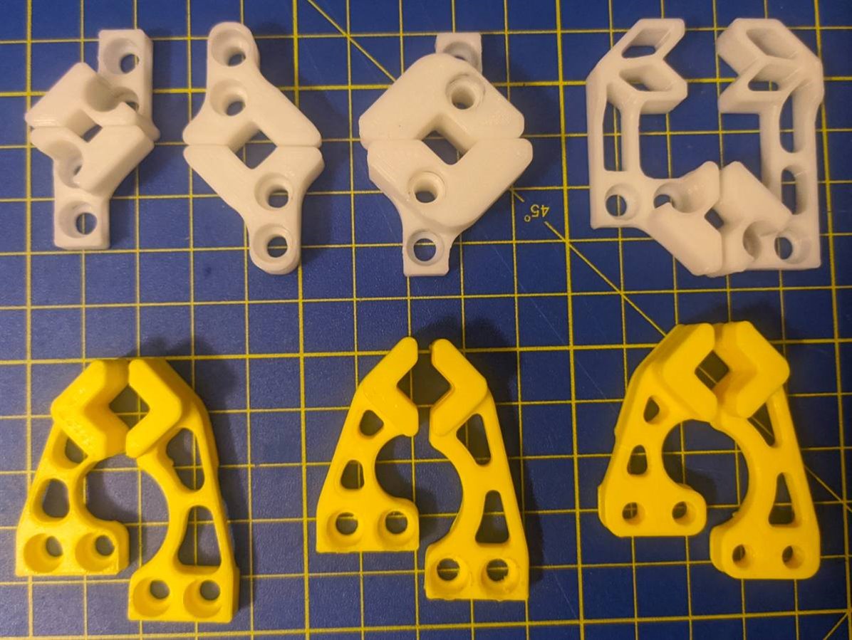
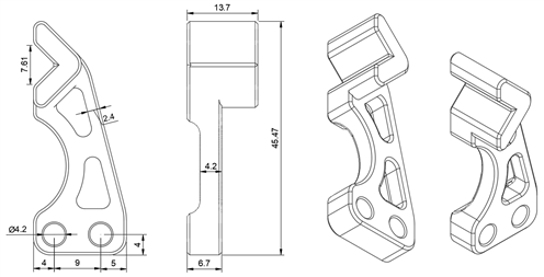
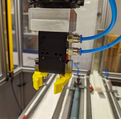
I designed the fingers to have a 90 degree angle where they are supposed to grab the pieces, this is intentional, because this will allow me for some room for mistakes when placing down the puzzle pieces. When you like at it from a perspective of the puzzle piece, there will be 4 sides coming towards you, all at a 45 degree angle, which will push around the part centering it perfectly. The gripper that was used in the end was the one on the far right. Here are some technical drawings as well as how it looks mounted to the robot.

Besides the gripper mockup that I talked about, I also did a 3D model assembly as an additional test (I'm aware that the 3D model check was enough, but why pass an opportunity to try and design a gripper with the same movement like the real one).
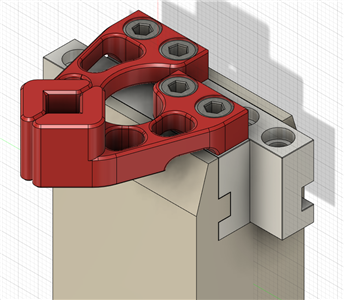
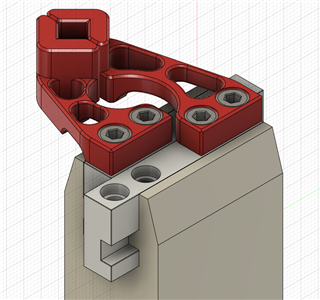
For designing all of the models I used Fusion360, as for the printing, I used my Ender3 Pro, with Creality yellow PLA. The models did require a bit of support, because there was an arch on the bottom side. The purpose of that arch was to make sure that the finger doesn't rub on the other rail while the gripper is operating. Here is how everything looks mounted on the robot.
4. Testing
Now finally comes the fun part, testing this on the robot. Well, before actually testing this on the robot, we had to program the robot in RobotStudio and do a simulation with the 3D model of our robot cell imported, to make sure everything would work great and that we don't have any collisions. Here are 2 videos of the robot working. The first video is it operating at 10% of it's programmed speed, which is why we were able to be next to the robot. We had to make some adjustments to the positions so everything would fit together as we wanted. After we made sure that that worked, we got out, turned the key to switch the robot to the automatic mode, which means we can utilize full robot speed and tried to see how fast the robot can go. As you can see from the second video, really fast.
5. Summary
This was a really cool class with a really cool project for the end of it. I'm sad I didn't film more stuff in the beginning when were testing out the robot, but seeing the tip of the tool on the robot follow a straight line mid air just doesn't look real to my eyes. I had this videos and I found them cool, specially the second fast one, so I thought I would share it here in a short blog for others to see. Thanks for reading this short blog, I hope you found it interesting!
Milos
Top Comments