Part 1 – RoadTest Rohde & Schwarz NGL201 Power Supply
This is the first blog post in a series that will cover my work for road testing the NGL201 power supply. I am planning to have three parts, so there will be two more parts that I will post as soon as I get the corresponding work done and documented. This part will cover a theoretical tutorial of power supplies, the unpacking of the NGL201 power supply, and a first set of measurements.
A Short Power Supply Theoretical Tutorial
What is a Power Supply
A power supply includes a sourcing function, a measurement function, and clamping/protection for maximum current. The source function in a simplistic approximation can be viewed as an ideal voltage source in series with a parasitic resistance. The parasitic resistance is “unwanted” here, and a lot of effort is made during design to reduce the value of this resistance. The measurement function includes a voltage measurement function and a current measurement function. The current clamping function limits the output current at a programmed value. When the power supply enters into this current limit mode, it functions as a constant current source. The output voltage may continue to increase but the current will be limited to the programmed value. A simplified diagram of a power supply is shown in the figure below.

The “A” branch symbolizes the power supply functionality in the current limit mode. The voltage measurement function can probe either the “Force High” and “Force Low” outputs of the power supply or it can probe the external load using two additional wires “Sense High” and “Sense Low”. The voltage measurement using the external sense wires represents the actual voltage at the load. The internal voltage measurement represents the voltage at the power supply outputs, which includes the voltage at the load plus the V=IR voltage drops on the wires that connect the external load to the power supply.
Operation modes of Power Supplies
If we plot voltage on the vertical axis of a graph and current on the horizontal axis, we can divide the graph in four regions or quadrants: positive voltage and positive current forms quadrant 1, positive voltage and negative current forms quadrant 2, negative voltage and negative current forms quadrant 3, and negative voltage and positive current forms quadrant 4. The following figure shows a diagram of the four quadrants defined above. A power supply functions in quadrants 1 and 3. Functionality in all quadrants is achieved by source measurement units (SMU). An SMU can function as a power supply when in quadrants 1 and 3 and it can also function in quadrants 2 and 4. The figure below illustrates the four quadrant operation regions and specifies in which quadrants a power supply operates and in which quadrants an SMU operates.

For simplicity in this diagram the power supply and SMU are illustrated with two output pins, “force high” and “force low”. Later the “sense high” and “sense low” pins will be considered in the block diagrams and circuit schematics. The horizontal axis represents the current flowing out of the force high connector and the vertical axis represents the voltage measured between the force high and force low pins. Let’s take a look in more details at these operation modes:
Quadrant 1
A power supply operating in quadrant 1 can function as either a voltage source or a current source. The power supply operates in force voltage mode when it provides a positive output voltage, and the external load is a passive circuit (no energy sources). The current flows out of the force high pin, then through the external load, and then it closes the loop by flowing back into the power supply through the force low pin. When the power supply enters in current limitation or clamping mode, it functions like a current source. In this mode the current is constant at the programmed limit/clamp value and the voltage will vary (at lower levels than the “open” load programmed value.
Quadrant 3
The operation in quadrant 3 is very similar to the operation in quadrant 1 with the difference that the programmed voltage is a negative value. Therefore, the direction of the current is opposite, current flows out of the power supply through the force low pin and it flows back into the SMU through the force high pin.
Quadrant 2
Power supplies cannot function in quadrant 2; only SMUs function in this quadrant. When the external circuit contains energy sources depending on the voltage/current settings in the SMU the electric current may flow into the force high pin of the SMU. In this case the SMU instrument operates as an electronic load. Depending on the external circuit and the SMU voltage and current limit settings if the voltage is positive and the current flows into the force high pin the SMU operates in quadrant 2. We need to notice here that depending on the impedance of the external circuit and the current limit setting on the SMU the SMU may operate in current limit mode (electronic current load) or in resistive load.
Quadrant 4
Quadrant 4 also applies only to SMUs since power supplies cannot operate in this quadrant. The operation in quadrant 4 involves external circuit that contains energy sources, and the polarity of these energy sources are so that the electric current flows into the force low pin of the SMU. The SMU operates as current load or resistive load depending on the voltage and current limit settings.
In the discussion above I have intentionally omitted the sense pins for simplicity. The sense pins were assumed to be connected to the force outputs of the power supply (or SMU). The voltage measured by the power supply or SMU was the voltage at the force high and force low pins, as shown in the diagrams above. In these cases, if there is a voltage drop on the wires to the external circuit under test or load, that voltage drop difference may affect the accuracy of the measurements. For these cases the power supplies and SMU instruments use sense pins, sense high and sense low, that the user can connect to the pins of the load. This way, the measured voltage is right at the pins of the load and the voltage drops on the force interconnect wires do not alter the measured values. The diagram below shows the operation of power supplies and SMUs in the four quadrants including the sense lines. Notice that the measured voltage is now at the external circuit pins and not at the SMU force high/low output pins.

Differences between power supplies and SMUs
SMUs integrate the function of a power supply, but they differ from typical power supplies by speed, precision, operation range, and four quadrant versus two-quadrant operation. SMUs are faster so that typically they settle within microseconds while power supplies settle in much longer time within milliseconds. This is important in measurements that use sweeping of voltage or current. The measurement accuracy is significantly higher for SMUs than for power supplies, typically for currents SMUs measurement accuracy is in the order of nanoamperes while for power supplies is in the order of microamperes. But probably the most important difference is the operation in four quadrants versus power supplies that operate only in two quadrants (quadrant 1 and 3). This is important for I-V curve tracing where some devices may operate in all four quadrants. Additionally, this is important for battery testing since batteries can source current and thus may require operating in quadrants 2 and 4.
Unpacking the Rohde & Schwarz NGL201 Power Supply and First Power UP
In this section I will describe my experience unpacking and powering up the R&D NGL201 power supply and turning it on for the first time. The package came announced by an email from Element14, so I knew when to look for it on the porch. The package was quite big so I have opened it and inside I have found another box which reading on the label it showed that it contains the Rohde & Schwarz NGL201 instrument. I then opened this box and inside indeed it was the R&D NGL201 instrument packed very well around with a thick polystyrene foam structure, as shown in the figure below.

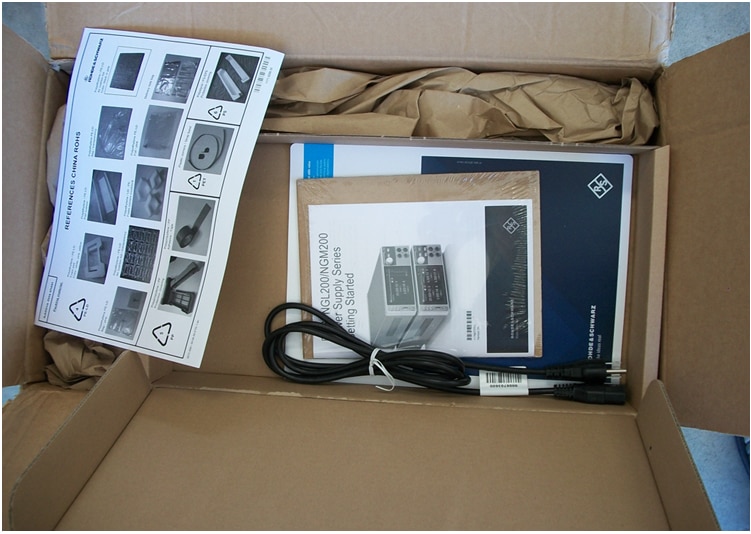
A separate box contained a power cable, a getting started guide, and a folder with the calibration certificate and list of license keys.

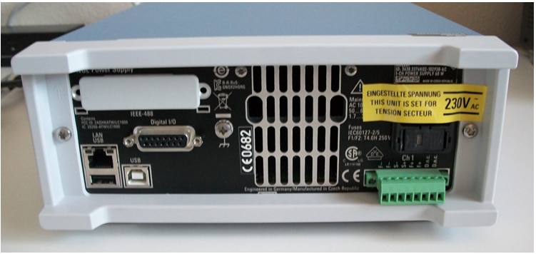
The first thing I needed to do was to adjust the settings for the US power voltage standard. On the back panel of the NGL201 power supply I have noticed a label mentioning that this instrument is set for operating at 230V, which was different than the 120V that I have here in the US.

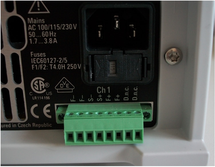
I knew how to set up the voltage selector on the back instrument from a previous experience with a similar instrument. So I started from where the 230V label was and I figured out that if I push on that plastic structure it slides out of the instrument.

So that piece of plastic came out and it held two fuses. Then, exploring more what came out, I have figured out that it was made of two pieces, one sliding into the other, as shown in the picture below.

After removing the inside piece (that was holding one of the fuses) I noticed three numbers printed on it that were corresponding to the three voltages listed in the getting started user guide. From this point it was easy – I just plugged the small plastic piece back into the big one making sure that the number 115 shows in the window, as show in the picture below.

And then I have plugged it back into the NGL201 instrument.

Then I have plugged the NGL201 power cable into the power outlet and I pressed the power button – and it worked:
I am now ready to start the next steps of performance evaluation and measurement experiments.

Getting Started with Measurements
I have started with a few simple measurements that have setup the R&S NGL201 Power supply to operate into quadrant1 and 3 explained in the first section above. Here are the details:
Quadrant 1


For operation in quadrant 1 I have setup the NGL201 to force a positive voltage, 1V, and I connected an external 2 Ohms resistor between the force high and force low connectors. In this experiment intentionally I did not use the sense lines. The displayed current was 0.446A while the calculated value was 1V/2Ohms = 0.5A. The difference comes from the wire resistance, which we can roughly calculate here as 1V/0.446A – 2 Ohms = 0.24 Ohms for both wires, so 0.12 Ohms per each wire.
Quadrant 3
The operation in Quadrant 3 is setup similarly to the operation in Quadrant 1 with the only difference that the + and – wire connections are reversed so that the voltage applied to the load has a negative value. Therefore, the current will also have a negative value, which makes the NGL201 operate in Quadrant 3.
Four Wire Connection
In the measurements above we have noticed that the wire resistance produced voltage drops of about 0.24Ohms x 0.446A = 0.1V, so when we programmed 1V on the power supply the actual voltage applied to the load resistor was only 0.9V. To eliminate this effect the NGL201 power supply can be configured with 4 wire connection so that the sense voltage is located at the load instead of at the instrument output terminals. The 4 wire configuration is illustrated in the diagram below:

And the modified measurement setup is shown in the following figure:

Let’s notice now that the current has increased to 0.498A, which is close to the calculated value of 1V/2Ohms=0.5A. The NGL201 shows a measured voltage of 1V (0.99991V). This is the voltage at the load. The power supply has to send a higher voltage to compensate for the voltage drop on the wires, so that at the load the voltage is 1V. To understand this let’s bring an external DMM and measure the voltages at the NGL201 terminals and at the load. The DMM measurement at the NGL201 terminals are shown the figure below:

The DMM measures 1.036V at the NGL201 terminals. Let’s move the DMM to the load:

The DMM measures 1V at the load. This value correlates with the reading on the NGL201 screen, which comes in line with the assumption that when using 4 wires connection the NGL201 displays the voltage measured at the load. So the NGL201 has to send a higher voltage, 1.036V, through the wires in order to have 1V at the load. The sense lines monitor continuously the voltage at the load and the NGL201 power supply adjusts the voltage at its output terminals so that the voltage at the load is maintained at 1V even when the load current changes.
This is the first update on this road test review work. I will come back with new updates as I get more work done.
Best Wishes,
Cosmin
