element14 Community
element14 Community
    Register Log In
  • Site
  • Search
  • Log In Register
  • About Us
  • Community Hub
    Community Hub
    • What's New on element14
    • Feedback and Support
    • Benefits of Membership
    • Personal Blogs
    • Members Area
    • Achievement Levels
  • Learn
    Learn
    • Ask an Expert
    • eBooks
    • element14 presents
    • Learning Center
    • Tech Spotlight
    • STEM Academy
    • Webinars, Training and Events
    • Learning Groups
  • Technologies
    Technologies
    • 3D Printing
    • FPGA
    • Industrial Automation
    • Internet of Things
    • Power & Energy
    • Sensors
    • Technology Groups
  • Challenges & Projects
    Challenges & Projects
    • Design Challenges
    • element14 presents Projects
    • Project14
    • Arduino Projects
    • Raspberry Pi Projects
    • Project Groups
  • Products
    Products
    • Arduino
    • Avnet Boards Community
    • Dev Tools
    • Manufacturers
    • Multicomp Pro
    • Product Groups
    • Raspberry Pi
    • RoadTests & Reviews
  • Store
    Store
    • Visit Your Store
    • Choose another store...
      • Europe
      •  Austria (German)
      •  Belgium (Dutch, French)
      •  Bulgaria (Bulgarian)
      •  Czech Republic (Czech)
      •  Denmark (Danish)
      •  Estonia (Estonian)
      •  Finland (Finnish)
      •  France (French)
      •  Germany (German)
      •  Hungary (Hungarian)
      •  Ireland
      •  Israel
      •  Italy (Italian)
      •  Latvia (Latvian)
      •  
      •  Lithuania (Lithuanian)
      •  Netherlands (Dutch)
      •  Norway (Norwegian)
      •  Poland (Polish)
      •  Portugal (Portuguese)
      •  Romania (Romanian)
      •  Russia (Russian)
      •  Slovakia (Slovak)
      •  Slovenia (Slovenian)
      •  Spain (Spanish)
      •  Sweden (Swedish)
      •  Switzerland(German, French)
      •  Turkey (Turkish)
      •  United Kingdom
      • Asia Pacific
      •  Australia
      •  China
      •  Hong Kong
      •  India
      •  Korea (Korean)
      •  Malaysia
      •  New Zealand
      •  Philippines
      •  Singapore
      •  Taiwan
      •  Thailand (Thai)
      • Americas
      •  Brazil (Portuguese)
      •  Canada
      •  Mexico (Spanish)
      •  United States
      Can't find the country/region you're looking for? Visit our export site or find a local distributor.
  • Translate
  • Profile
  • Settings
Personal Blogs
  • Community Hub
  • More
Personal Blogs
Cosmin Iorga's Blog RoadTest the Advantech PCIE-1816 - Part 2 Signal measurements with Advantech PCIE-1816 DAQ card and DAQNavi software
  • Blog
  • Documents
  • Mentions
  • Sub-Groups
  • Tags
  • More
  • Cancel
  • New
  • Share
  • More
  • Cancel
Group Actions
  • Group RSS
  • More
  • Cancel
Engagement
  • Author Author: ciorga
  • Date Created: 30 Nov 2016 6:02 AM Date Created
  • Views 1275 views
  • Likes 2 likes
  • Comments 4 comments
  • pcie-1816daq
  • data acquisition
  • advantech
  • daq
  • pcie daq card
  • pcie-1816
Related
Recommended

RoadTest the Advantech PCIE-1816 - Part 2 Signal measurements with Advantech PCIE-1816 DAQ card and DAQNavi software

ciorga
ciorga
30 Nov 2016

This is the second blog post in a series of three covering my road test evaluation of Advantech PCIE-1816 DAQ card and DAQNavi software.  In this blog post I am planning to cover signal measurements with the PCIE-1816 DAQ card and DAQNavi software.


After mounting the PCIE-1816 DAQ board in the computer and installing the DAQNavi software I started with a simple measurement of a DC voltage source.  First I had to configure the inputs of the DAQ board, and I found quite useful the “PCIE1816_User_interface.pdf” document, in which I found “visual” diagrams showing how to connect signals to the DAQ board inputs, like the example below:


image

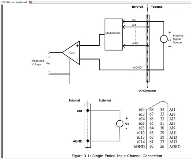
Based on this diagram I connected my voltage supply to AI0 at pin 68, and I used pin 60 for ground:


image

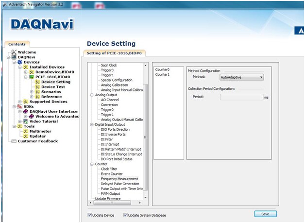
I then opened the DAQNavi input setup panel and I set the input voltage range on channel 0 to +/-10V:


image

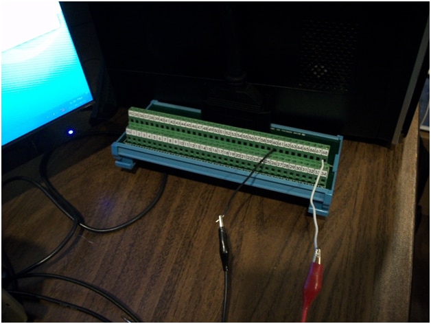
I then setup 6V on a power supply and I connected a Fluke DMM also on the inputs into the DAQ board.  My setup is shown in the picture below:


image

On the left side computer screen I kept the PCIE1816_User_interface.pdf document open and on the right side screen I opened DAQNavi program.  This picture shows the Multimeter function of the DAQNavi software, which measures 6.076V.  The Fluke DMM measures 6.073V, close to the DAQNavi Multimeter measurement. 

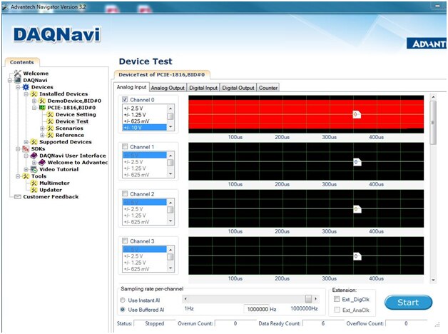
I then used the DAQNavi transient graph window to display the 6V dc input signal, as shown in the screenshot below:


image

Notice the red trace in the upper graph that started from the left side and moved towards the right as more samples have been recorded.  The built-in cursor function shows 5.9V, which is close to 6V considering also the visual approximation of me aligning that cursor with the signal trace.

After measuring this 6V dc signal I moved towards more advanced measurements.  Next, I measured a sinusoidal signal from a function generator, as shown in the test bench picture below:


image

I have also used an oscilloscope to visualize the signal applied to the DAQ board.  The signal displayed on the oscilloscope is shown in the picture below:


image

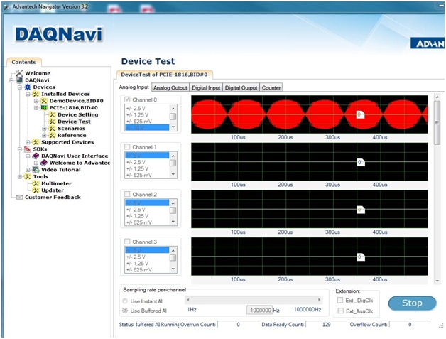
And the same signal measured with the Advantech 1816 DAQ board and DAQNavi software is shown in the picture below:

image


Comparing the DAQ card measured waveform with the oscilloscope waveform, the sinusoid period is 5 x-axis divisions of 100us/div on the DAQNavi graph, close to 497us on the oscilloscope.  The low level is -3.18V on the DAQNavi graph close to 3.16V on the oscilloscope.  The upper level is 3.18V on the DAQNavi graph, as shown below,


image

which was close to 3.20V on the oscilloscope.

I then increased the frequency to “push” into the Nyquist sampling rate.  So the max sampling rate of the 1816DAQ card is 1Ms/s, so I increased the generator frequency to 500kHz.  At this setting I ran into stability issues, since it looked like the generator could not keep a constant 500kHz frequency.  By manual continuous adjustment I could temporarily maintain 500kHz, like in the screenshot below:

image


But most of the time I couldn’t, so my sampled waveform looked like this:


image

Next I evaluated external trigger functions of the Advantech 1816 DAQ card.  Again, I found very useful the “PCIE1816_User_interface.pdf” document, which shows in simple to quickly understand the connections for external analog and digital trigger:


image


The rest of trigger settings I have done in DAQNavi settings panel, which uses a great graphical interface to quickly show how the trigger works and what each setting means.  The panel for setting the digital trigger is shown in the screenshot below:


image

And for the analog trigger:


image

I have looked at various waveform frequencies and trigger settings; here is one example with digital trigger:


image

And the corresponding input signal (yellow) and trigger signal (blue):


image

After finishing the measurement of analog signals I looked into measuring digital signals.  The DAQNavi software has a nice graphical interface for displaying the logic state at the digital inputs, and which has a pattern matching feature.  In this experiment I toggled bit 0 of port 0, so the input pattern changed from 0xFF to 0xFE (hex representation).  I opened the DAQNavi settings panel and I setup the pattern recognition to look for 0xFE pattern:


image

With these settings I then turned on my frequency generator and the DAQNavi software started to display how many matched patterns have been recorded:


image

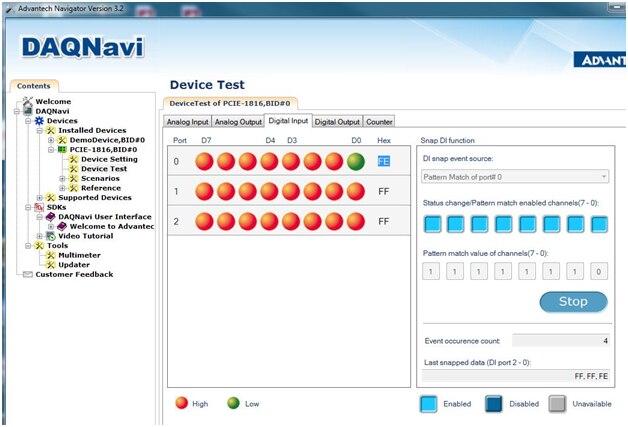
Notice the “Event occurrence count” = 4 (and it kept going up as more bit toggling occurred).


Next I setup the 1816 DAQ board counter to measure the frequency of a digital input signal.  The counter can perform various other measurements like: event counting, one shot, timer/pulse, pulse width.  In this experiment I chose to measure the frequency of a signal provided by an external frequency generator. 


image


Here is the DAQNavi measurement panel:


image

The measured frequency was 238Hz, and the same signal frequency measured with the oscilloscope was also 238kHz, as shown in the picture below:


image

Overall I was very impressed of the performance of measuring signals with the Advantech 1816 DAQ card and the easy to setup these measurements in DAQNavi software.  The pdf user guide was very clear and of a significant help.


This concludes the second of the three blog posts I planned for this review/evaluation.  That’s it for now; I will come back and continue with my next steps in evaluations this PCIE-1816 DAQ card as soon as I get more work done.

Best Wishes,

Cosmin

  • Sign in to reply

Top Comments

  • DAB
    DAB over 8 years ago +1
    Great post Cosmin. I had a wild thought, what if you applied the same AC signal to all of the inputs and set them up to all sample at the same rate. What I am interested in is if the multiplexer can keep…
  • DAB
    DAB over 8 years ago in reply to ciorga

    Cool, that means they did a good design with the internal sample and hold circuits so that they do not degrade at fast switching rates.


    Much thanks,


    DAB

    • Cancel
    • Vote Up 0 Vote Down
    • Sign in to reply
    • More
    • Cancel
  • ciorga
    ciorga over 8 years ago in reply to DAB

    Hi DAB,

    I have run the experiment you have proposed and I haven't seen any noticeable degradation or phase shift for same signal sampled with multiple channels.  I have a screenshot showing the first four channels:

    image

    Best Wishes,

    Cosmin

    • Cancel
    • Vote Up 0 Vote Down
    • Sign in to reply
    • More
    • Cancel
  • ciorga
    ciorga over 8 years ago in reply to DAB

    Hi DAB,

    Thank you for your comments; this is a great experiment that will show how the simultaneous sampling performs.  Thank you for sharing this idea of measurement.  I will perform it and come back with the results.

    Best Wishes,

    Cosmin

    • Cancel
    • Vote Up 0 Vote Down
    • Sign in to reply
    • More
    • Cancel
  • DAB
    DAB over 8 years ago

    Great post Cosmin.


    I had a wild thought, what if you applied the same AC signal to all of the inputs and set them up to all sample at the same rate.


    What I am interested in is if the multiplexer can keep up with the sampling so that there is no signal digitization degradation as you use all of the channels.


    Just a thought,


    DAB

    • Cancel
    • Vote Up +1 Vote Down
    • Sign in to reply
    • More
    • Cancel
element14 Community

element14 is the first online community specifically for engineers. Connect with your peers and get expert answers to your questions.

  • Members
  • Learn
  • Technologies
  • Challenges & Projects
  • Products
  • Store
  • About Us
  • Feedback & Support
  • FAQs
  • Terms of Use
  • Privacy Policy
  • Legal and Copyright Notices
  • Sitemap
  • Cookies

An Avnet Company © 2025 Premier Farnell Limited. All Rights Reserved.

Premier Farnell Ltd, registered in England and Wales (no 00876412), registered office: Farnell House, Forge Lane, Leeds LS12 2NE.

ICP 备案号 10220084.

Follow element14

  • X
  • Facebook
  • linkedin
  • YouTube