


Project Objective: Develop an open source AIS Alarm that alerts sailors that a new marine vessel with AIS is within range
The prototype now receives AIS messages from the dAISy module and stores them in a persistent FRAM ring buffer. The ring buffer will be described in this post and code to test the concept by emptying the ring buffer and displaying it implemented.
The ring buffer uses an algorithm presented by Jack Ganssle in Embedded Muse 110 and published in 2005. I have modified it for use with strings and removed the check for a full buffer so that it continues to wrap. The oldest entries are deleted and the most recent kept. I am still playing with the code and not everything is working as intended. The basic API looks like this:
void          initMsgBuf(void);                // buffer initiation (flushes buffer)
void          putMsgBuf(char newMsg[]);        // puts new message into buffer
char *        getMsgBuf(void);                 // returns/removes first message from buffer
inline int    msgBufIsEmpty(void);             // returns -1 if buffer is empty
inline int    msgBufLength(void);              // number of entries in buffer
As AIS messages come in, they are put into the buffer with putMsgBuf(). When the user pushes the display button getMsgBuf() is used to output messages stored in the ring buffer over UART. And of course initMsgBuf() can be used to initialize or flush the buffer of contents.
The modified functions follow:
// Function to initialize and flush the buffer
// ---------------------------------------------------------------------
void initMsgBuf(void){
  FRAM_enableWrite();
  msgBufHead = 0;
  msgBufTail = 0;
  FRAM_disableWrite();
}
// Function to put an entry into the buffer
// ---------------------------------------------------------------------
void putMsgBuf(char newMsg[]){
  FRAM_enableWrite();
  strcpy(nmea[msgBufHead & (MBUF_SIZE - 1)].msg, newMsg);
  msgBufHead++;
  FRAM_disableWrite();
}
// Function to get an entry from the buffer
// ---------------------------------------------------------------------
char * getMsgBuf(void){
  FRAM_enableWrite();
  msgBufTail++;
  FRAM_disableWrite();
  return nmea[(msgBufTail - 1) & (MBUF_SIZE - 1)].msg;
}
// Function to determine if the buffer is empty
// ---------------------------------------------------------------------
inline int msgBufIsEmpty(void) {
  if (msgBufLength() == 0) {
    return MBUF_EMPTY;
  }
  return 0;
}
// Function to determine the number of entries in the buffer
// ---------------------------------------------------------------------
inline int16_t msgBufLength(void) {
  return msgBufHead - msgBufTail;
}
Note that FRAM_enableWrite() and FRAM_disableWrite() are used when writing to the buffer to give some protection since FRAM also contains program instructions.
I am not ready to publish the entire listing as it is in a raw state and still being tested. The items that are still being cleared up include:
- A new message can come in over UART while the ring buffer is being emptied and move a Head / Tail pointer. Need to decide how to handle this (e.g. ignore or somehow capture new messages while the ring buffer empties).
- Power could be unplugged while the device is being connected to a PC. This could happen while a new message is coming in over UART and that entry could be corrupted. Need to decide how to handle this.
- Currently the variables that point to the Head and Tail of the ring buffer are changed as the buffer is "emptied". In reality it isn't emptied and the old messages could be kept by restoring msgBufHead and msgBufTail. The design criteria say this data should be kept until the user resets.
- msgBufHead and msgBufTail require modifications in the event of a full buffer that have not been made yet.
- msgBufHead and msgBufTail are not checked for overflow
There is time to resolve these issues while the enclosure and hardware designs are advanced. When the hardware design is firmer I intend to ask a friend who is an experienced C programmer to do a code review with me and refactor as needed.
The following screen shot is a demonstration of the current state of the firmware. It shows the incoming messages (RX) from dAISy on the second line of the logic analyzer. When the display button is pushed, output of what is stored in the ring buffer (TX) shows up on the top line.
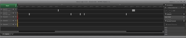
The first series of blips on the second line is a single incoming message from dAISy. In this case the ring buffer was empty when this occurred. The next series of blips is on the top line and occurred when the display button was pushed. Closer inspection shows it to be identical to the message just received. The ring buffer was emptied during the output. Following that are four blips on the second line that represent four more incoming AIS messages. When the display button was pushed the second time these four messages came out together on the top line, again identical to what was received.
Now that the concept seems valid it is time to progress the hardware and also get more feedback from a potential user on the user interface. As previously stated, the developer of dAISy openly encourages projects like this and has been contacted for input as well.
If you have been waiting for something a bit more hardware oriented then that is coming up. Thanks for reading and as always comments and suggestions are welcome.
EDITED on 2018/Jan/6 to update code status
Past Posts from this Project:
AIS Alarm - Prototype Hardware
AIS Alarm - Prototype Code Outline
AIS Alarm - First AIS Messages
AIS Alarm - First FRAM Storage
AIS Alarm - Debouncing Momentary Button Switches
References and Links:
WEGMATT LLC - dAISy AIS Receiver - low cost AIS receiver
Texas Instruments MSP430FR2xx FRAM Microcontrollers - Post No. 4
Top Comments