element14 Community
element14 Community
    Register Log In
  • Site
  • Search
  • Log In Register
  • Community Hub
    Community Hub
    • What's New on element14
    • Feedback and Support
    • Benefits of Membership
    • Personal Blogs
    • Members Area
    • Achievement Levels
  • Learn
    Learn
    • Ask an Expert
    • eBooks
    • element14 presents
    • Learning Center
    • Tech Spotlight
    • STEM Academy
    • Webinars, Training and Events
    • Learning Groups
  • Technologies
    Technologies
    • 3D Printing
    • FPGA
    • Industrial Automation
    • Internet of Things
    • Power & Energy
    • Sensors
    • Technology Groups
  • Challenges & Projects
    Challenges & Projects
    • Design Challenges
    • element14 presents Projects
    • Project14
    • Arduino Projects
    • Raspberry Pi Projects
    • Project Groups
  • Products
    Products
    • Arduino
    • Avnet Boards Community
    • Dev Tools
    • Manufacturers
    • Multicomp Pro
    • Product Groups
    • Raspberry Pi
    • RoadTests & Reviews
  • Store
    Store
    • Visit Your Store
    • Choose another store...
      • Europe
      •  Austria (German)
      •  Belgium (Dutch, French)
      •  Bulgaria (Bulgarian)
      •  Czech Republic (Czech)
      •  Denmark (Danish)
      •  Estonia (Estonian)
      •  Finland (Finnish)
      •  France (French)
      •  Germany (German)
      •  Hungary (Hungarian)
      •  Ireland
      •  Israel
      •  Italy (Italian)
      •  Latvia (Latvian)
      •  
      •  Lithuania (Lithuanian)
      •  Netherlands (Dutch)
      •  Norway (Norwegian)
      •  Poland (Polish)
      •  Portugal (Portuguese)
      •  Romania (Romanian)
      •  Russia (Russian)
      •  Slovakia (Slovak)
      •  Slovenia (Slovenian)
      •  Spain (Spanish)
      •  Sweden (Swedish)
      •  Switzerland(German, French)
      •  Turkey (Turkish)
      •  United Kingdom
      • Asia Pacific
      •  Australia
      •  China
      •  Hong Kong
      •  India
      •  Korea (Korean)
      •  Malaysia
      •  New Zealand
      •  Philippines
      •  Singapore
      •  Taiwan
      •  Thailand (Thai)
      • Americas
      •  Brazil (Portuguese)
      •  Canada
      •  Mexico (Spanish)
      •  United States
      Can't find the country/region you're looking for? Visit our export site or find a local distributor.
  • Translate
  • Profile
  • Settings
Personal Blogs
  • Community Hub
  • More
Personal Blogs
Frank Milburn's Blog AIS Alarm - Schematic
  • Blog
  • Documents
  • Mentions
  • Sub-Groups
  • Tags
  • More
  • Cancel
  • New
  • Share
  • More
  • Cancel
Group Actions
  • Group RSS
  • More
  • Cancel
Engagement
  • Author Author: fmilburn
  • Date Created: 12 Jan 2018 6:25 AM Date Created
  • Views 918 views
  • Likes 6 likes
  • Comments 4 comments
Related
Recommended

AIS Alarm - Schematic

fmilburn
fmilburn
12 Jan 2018

Project Objective: Develop an open source AIS Alarm that alerts sailors that a new marine vessel with AIS is within range


The breadboard prototyping and first pass at firmware are sufficient to proceed to hardware design.  After exchanges with the developer of dAISy and some early layout I have modified the pins used by the microcontroller and foresee the need to refactor the firmware.  At this point though no show stoppers are foreseen.  This post will describe the preliminary schematic and what drove some of the decisions.

image

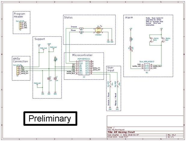
On the left is a programming header for the MSP430FR2111 and a pin header for connecting to the dAISy module.  The MSP430FR2111 will be programmed with pogo pins and the connection with the dAISy module will be by ribbon cable.  The support circuity for the microcontroller is the same as in previous posts with the addition of a 5V rail which will be used to drive the alarm buzzer and LED.  Status is given by dual LED right angle indicator driven directly from the microcontroller.  User input is from two right angle momentary switches.  The alarm will have a right angle LED drawing around 25 mA.  The PCB will have a footprint for both SMD and through hole parts as a final decision has not been made.  Current will be on the order of 25 mA and I will probably alternate beeping the buzzer with blinking the alarm LED to minimize current draw.


I received excellent feedback from element14 member in this thread on how to maximize the sound from a buzzer.  Among the suggestions I have incorporated in the design are 1) use of a N channel MOSFET instead of a NPN transistor, 2) maximizing current within the constraints of my supply, and 3) a search for the most efficient piezo buzzer I could find that fit the design.


Past Posts from this Project:

AIS Alarm

AIS Alarm - The Process

AIS Alarm - Prototype Hardware

AIS Alarm - Timers and GPIO

AIS Alarm - Prototype Code Outline

AIS Alarm - UART

AIS Alarm - First AIS Messages

AIS Alarm - First FRAM Storage

AIS Alarm - Debouncing Momentary Button Switches

AIS Alarm - FRAM Ring Buffer


References and Links:

WEGMATT LLC - dAISy AIS Receiver - low cost AIS receiver

Texas Instruments MSP430FR2xx FRAM Microcontrollers - Post No. 4

TI MSP430FR2111

Maximize the Sound from a Buzzer

  • Sign in to reply

Top Comments

  • three-phase
    three-phase over 7 years ago +2
    Nice clear well labelled schematic. Excellent to see you incorporating advice from previous posts, there are some amazing talented helpful people on here. Kind regards
  • fmilburn
    fmilburn over 7 years ago in reply to three-phase +1
    Thanks and agreed, it is a very helpful and supportive community
  • genebren
    genebren over 7 years ago +1
    Frank, I love those dual mosfet packages. The pinout is such that you can not place them on the board incorrectly, i.e. the pinout is symmetrical. Too bad you did not need the other half of the set. G…
  • fmilburn
    fmilburn over 7 years ago in reply to genebren

    Hi Gene, this is the first time I have used them (but it wouldn't be the first time I placed an IC on the board upside down so glad they are symmetric).  I will be driving the alarm LED with the MOSFET as it will be pulsing about 25 mA as well as the piezo buzzer.  It is amazing how many MOSFETs, even the dual ones, there are to chose from.

    • Cancel
    • Vote Up 0 Vote Down
    • Sign in to reply
    • More
    • Cancel
  • genebren
    genebren over 7 years ago

    Frank,


    I love those dual mosfet packages.  The pinout is such that you can not place them on the board incorrectly, i.e. the pinout is symmetrical.  Too bad you did not need the other half of the set.

    Gene

    • Cancel
    • Vote Up +1 Vote Down
    • Sign in to reply
    • More
    • Cancel
  • fmilburn
    fmilburn over 7 years ago in reply to three-phase

    Thanks and agreed, it is a very helpful and supportive community

    • Cancel
    • Vote Up +1 Vote Down
    • Sign in to reply
    • More
    • Cancel
  • three-phase
    three-phase over 7 years ago

    Nice clear well labelled schematic. Excellent to see you incorporating advice from previous posts, there are some amazing talented helpful people on here.


    Kind regards

    • Cancel
    • Vote Up +2 Vote Down
    • Sign in to reply
    • More
    • Cancel
element14 Community

element14 is the first online community specifically for engineers. Connect with your peers and get expert answers to your questions.

  • Members
  • Learn
  • Technologies
  • Challenges & Projects
  • Products
  • Store
  • About Us
  • Feedback & Support
  • FAQs
  • Terms of Use
  • Privacy Policy
  • Legal and Copyright Notices
  • Sitemap
  • Cookies

An Avnet Company © 2025 Premier Farnell Limited. All Rights Reserved.

Premier Farnell Ltd, registered in England and Wales (no 00876412), registered office: Farnell House, Forge Lane, Leeds LS12 2NE.

ICP 备案号 10220084.

Follow element14

  • X
  • Facebook
  • linkedin
  • YouTube