


*** UPDATED 2nd April 2018 - At bottom - first attempt at soldering QFN
*** UPDATED 14 June 2018 - At bottom - second attempt at soldering QFN - FAIL
*** UPDATED 16 June 2018 - At bottom - third attempt it's alive! See bottom of post for what was wrong and how it was repaired
For sometime I have been using the Texas Instruments MSP430G2553 in most of my projects. It is relatively inexpensive at $1.98 in small quantities, comes in DIP and TSSOP packages that can be hand soldered, and there is a community of users as well as good TI documentation and training. My two complaints are the amount of RAM (512 bytes) and the limited serial with hardware SPI and I2C being on the same pins. I seem to be bumping up against both problems more frequently these days and I am at the point where I am going to upgrade my base microcontroller. I want to keep cost to around $3 USD or less in small quantities.
I am considering three options:
- MSP430G2955 - I have used this microcontroller in the past and it is an easy upgrade and switch for me from the G2553. It has 56 KB Flash and 4096 bytes RAM in the 38-TSSOP package. It has hardware UART, SPI, and I2C available on separate pins. There is lots of I/O. The cost is $2.84 in small quantities. Probably won't select this.
- MSP430FR2433 - The subject of this blog. It has 15360 bytes program FRAM, 512 bytes information FRAM, and 4096 bytes SRAM. Hardware UART, SPI, and I2C are on separate pins. It has 8 channel 10-Bit ADC, four 16-Bit Timers, and 19 I/O with 16 interrupts. The cost is $2.37 in small quantities for the BGA package. Newark does not list the QFN package which I am using. I got mine earlier directly from TI. There is an upgrade path but the larger chips can get expensive. I like the FRAM microcontrollers and the smaller FR2111 which I am using in my AIS alarm is reasonably priced at less than a $1 but Newark does not seem to normally carry it.
- ARM M0+ - I have started playing around with the ATSAMD21 but of course there are a lot of other ARM chips out there. Cost varies but as an example this 32 pin TQFP with 32 KB RAM and 256 KB Flash is $3.07 in small quantities. I have much less familiarity but don't see the learning curve as too steep. It is also a more powerful microcontroller with plenty of IO. I did manage to solder a 32 pin TQFP on a protoboard once.
One of my concerns with the FR2433 is the ability to solder it. I am confident of my ability to do it with a stencil and toaster oven but buying a stencil adds a fair amount to the cost when only a couple of boards are being made. Besides, I like hand soldering.
Accordingly, last night I put designed a stripped down breadboard friendly breakout board for the QFN MSP430FR2433 package. It has a LED, a momentary switch, programming header, and access to all the pins. Everything else but the switch is 0805.
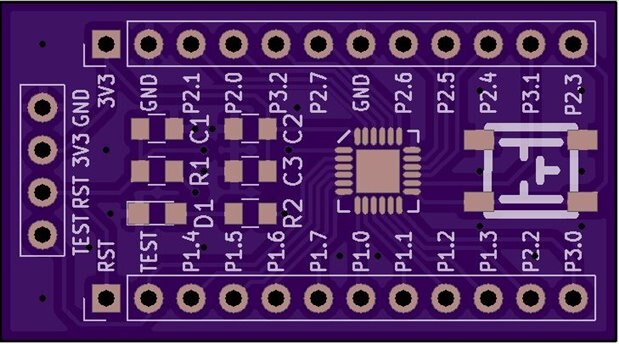
I modified the TI recommended footprint by slightly lengthening the pads. The large pad in the center of the QFN footprint is for mechanical and thermal purposes - it is not connected to a network. In a week or two I will find out whether I can solder a 0.5 mm pitch QFN by hand. I will also try doing one with my inexpensive rework station...
2nd April 2018 Update
I received the PCBs back and they look fine with all electrical connections testing OK.

Unfortunately, my first attempt at soldering did not work out as I can't get the package to "stick" well mechanically (no solder on the center pad) and the pin pads are not long enough to really get my soldering iron on them well. In the photograph above I have laid the 24 pin QFN package down on the foot print to indicate how far the pads are extended past the package. After failing with the iron I tried using the hot air rework station and didn't get good results with that either - for one thing I don't get good heat flow to the center pad and the solder I put there wasn't reflowing. Next step is to try it with an oven but that may be a while as I have too many projects going at once and need to concentrate on finishing some of the others.
14 May Update
I made another attempt to solder the package today and unfortunately had another failure. This is not a failure of the part, it is a failure of technique. I have been able to solder such things with my friend's toaster oven but I have been trying to do it by hand and without a stencil. The last time I tried using paste and I decided that might be the problem as the solder was old and not very fluid. As a result I was getting among other things bridging.
This time I tried tinning the pads, including the center pad, and then wicking it clean so there was no "hill" on the center pad. I then applied the chip and used the hot air to reflow. It looked good under magnification but CCS complained when I tried to flash it that the microcontroller was not recognized. I tried dragging some more solder with the iron but no luck. I suspect I have pads that are not making good connection with the pins on the QFN package but can't get in to probe the pins so I don't know if that is the issue or not.
16 May Update
Finally, confirmed the problem and got it fixed. Thanks to shabaz and mcb1 for suggestions and tips on the issue. I tried photographing the nonworking board in good light with the FR2433 QFN attached and unfortunately could not see the problem. I also dug out the finest tips I have and looked for shorts with my multimeter - found a short between TST and RST. I decided to get the hot air rework out and removed the offending part. This is what I saw:
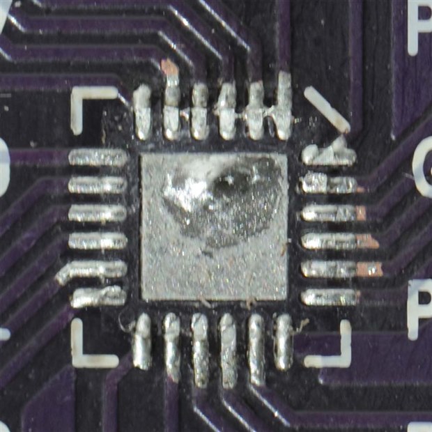
There are a couple of problems here...
- There is a solder pool on the center pad - I clearly did not wick enough of it away. There was also a tiny bit of solder on the underside of the QFN part that I had to wick away.
- There is bridging on the top row of pins. This was under the QFN part and I could not see it in photographs or with a lighted magnifier.
- I scraped so hard on the pins when trying to pull solder back from possible bridges with my iron that I scraped away solder mask. This was done before I removed the QFN part and usually does the trick for me with a TSSOP part.
The bridging is particularly bad because one of them is across the TST and RST pins as noted above. No wonder the IDE couldn't recognize the microcontroller.
So, I tried wicking away solder again. Here is the result:
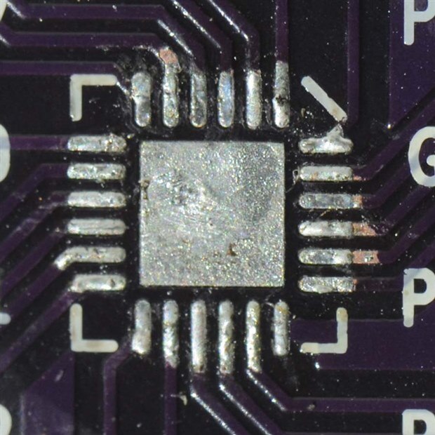
It looked better but I actually made one more pass with the wick before soldering it down. To solder I applied flux with a pen and then heated it for a bit without the FR2433 QFN on top. Then I placed the part and straightened it with the tweezers and gave it some more heat. And for good measure I pressed on the top of the package near the end of the heat cycle to make sure it was seated. I noted that this part does not self align with just the hot air reflow. But now, at last, it works and here it is...

Working MSP430FR2433 Breakout Board
Lesson Learned: Persistence paid off but at least for me, I need a stencil and a better means of reflow when working with QFN parts. And fresh paste probably wouldn't hurt. My limit for hand soldering seems to be TSSOP parts when it comes to packages. The pins, which stick out on TSSOP packages, make it easier for me to test as well as make a connection by hand.
Top Comments
-

fmilburn
-
Cancel
-
Vote Up
+5
Vote Down
-
-
Sign in to reply
-
More
-
Cancel
Comment-

fmilburn
-
Cancel
-
Vote Up
+5
Vote Down
-
-
Sign in to reply
-
More
-
Cancel
Children