element14 Community
element14 Community
    Register Log In
  • Site
  • Search
  • Log In Register
  • About Us
  • Community Hub
    Community Hub
    • What's New on element14
    • Feedback and Support
    • Benefits of Membership
    • Personal Blogs
    • Members Area
    • Achievement Levels
  • Learn
    Learn
    • Ask an Expert
    • eBooks
    • element14 presents
    • Learning Center
    • Tech Spotlight
    • STEM Academy
    • Webinars, Training and Events
    • Learning Groups
  • Technologies
    Technologies
    • 3D Printing
    • FPGA
    • Industrial Automation
    • Internet of Things
    • Power & Energy
    • Sensors
    • Technology Groups
  • Challenges & Projects
    Challenges & Projects
    • Design Challenges
    • element14 presents Projects
    • Project14
    • Arduino Projects
    • Raspberry Pi Projects
    • Project Groups
  • Products
    Products
    • Arduino
    • Avnet Boards Community
    • Dev Tools
    • Manufacturers
    • Multicomp Pro
    • Product Groups
    • Raspberry Pi
    • RoadTests & Reviews
  • Store
    Store
    • Visit Your Store
    • Choose another store...
      • Europe
      •  Austria (German)
      •  Belgium (Dutch, French)
      •  Bulgaria (Bulgarian)
      •  Czech Republic (Czech)
      •  Denmark (Danish)
      •  Estonia (Estonian)
      •  Finland (Finnish)
      •  France (French)
      •  Germany (German)
      •  Hungary (Hungarian)
      •  Ireland
      •  Israel
      •  Italy (Italian)
      •  Latvia (Latvian)
      •  
      •  Lithuania (Lithuanian)
      •  Netherlands (Dutch)
      •  Norway (Norwegian)
      •  Poland (Polish)
      •  Portugal (Portuguese)
      •  Romania (Romanian)
      •  Russia (Russian)
      •  Slovakia (Slovak)
      •  Slovenia (Slovenian)
      •  Spain (Spanish)
      •  Sweden (Swedish)
      •  Switzerland(German, French)
      •  Turkey (Turkish)
      •  United Kingdom
      • Asia Pacific
      •  Australia
      •  China
      •  Hong Kong
      •  India
      •  Korea (Korean)
      •  Malaysia
      •  New Zealand
      •  Philippines
      •  Singapore
      •  Taiwan
      •  Thailand (Thai)
      • Americas
      •  Brazil (Portuguese)
      •  Canada
      •  Mexico (Spanish)
      •  United States
      Can't find the country/region you're looking for? Visit our export site or find a local distributor.
  • Translate
  • Profile
  • Settings
Personal Blogs
  • Community Hub
  • More
Personal Blogs
Frank Milburn's Blog Working Prototype of a Kelvin (4-Wire) Milliohm Meter
  • Blog
  • Documents
  • Mentions
  • Sub-Groups
  • Tags
  • More
  • Cancel
  • New
  • Share
  • More
  • Cancel
Group Actions
  • Group RSS
  • More
  • Cancel
Engagement
  • Author Author: fmilburn
  • Date Created: 11 Oct 2018 12:33 AM Date Created
  • Views 5695 views
  • Likes 12 likes
  • Comments 26 comments
  • kelvin measurement
  • current source
  • 4 wire measurement
  • milliohm measurement
  • op amps
Related
Recommended

Working Prototype of a Kelvin (4-Wire) Milliohm Meter

fmilburn
fmilburn
11 Oct 2018

I am developing an inexpensive but reasonably accurate meter for measuring resistance in the milliohm range.  The three previous posts are listed in the related links at the bottom of this post.  In this post a working prototype is presented that has milliohm accuracy down to one millivolt.  A schematic and test data are presented along with plans for the next steps.


Current Status

That heading above is supposed to be a pun :-).  Much of the work since the last post is described in the comments of that post where a change was made to using the LM334 as a temperature compensated current source.  The design includes several suggestions from shabaz which worked out very well.  Shabaz also did a number of tests of the temperature coefficient of diodes and BJT transistors in TO92 packages which were used in the design.  The design calculations for a 10 mA current source using a spreadsheet developed for the LM334 are shown below:

image

A MCP6N16 instrument amp with 100x gain was then added as shown in the following schematic:

image

For now, power is USB from a wall wart.  There is an inline jumper so that a current meter can be inserted.  Provision is made for Kelvin probes as shown in the middle box far left.  A transistor is used to reduce power stress in the LM334 and a number of "Do Not Populate" resistor pads added to better allow trimming along with a potentiometer.  The MCP6N16 is in the middle of the sheet and uses the recommended resistors for 100x gain in the datasheet.  A useful aspect of the 100x gain is that with a 10 mA current source the output voltage reading can be directly converted to ohms (e.g. a 50 mV reading is equivalent to 50 milliohms).  Finally, there is a User Interface box at far right which for now consists of a bench multimeter.


The schematic was moved off of a breadboard and pieced together on a prototyping PCB placed in a cardboard box for further testing:

image

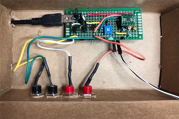
Since I only have one LM334 and MCP6N16 they are socketed for easy removal.  The resistors are mostly SMD and soldered between pads on the back.   All other components are soldered. Testing was done on what appears to be 26 AWG wire which I stripped off of something. A photo of the test apparatus is given below:

image

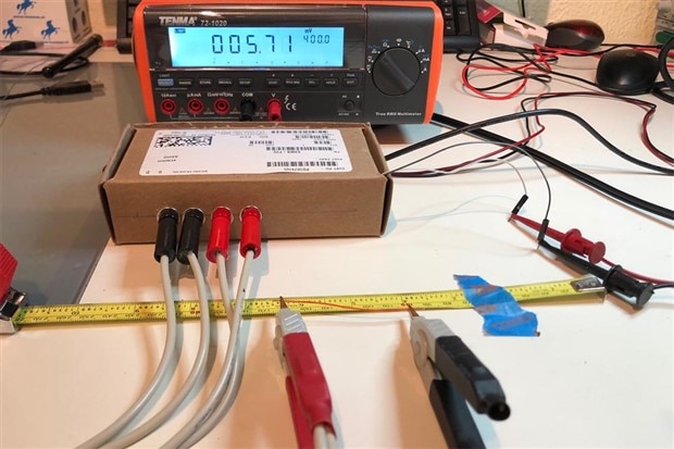
The prototype in its box is just below the multimeter in center.  The 4-wire Kelvin probes are seen connected to it.  The meter is connected to the output of the instrument amp by the red and black probes far right and the reading in millivolts is being displayed.  The procedure for the tests was to measure the length of wire on the tape and then connect it to the Kelvin probes and take a reading.  The wire in the photo is approximately 60 mm in length and the reading is 5.71 millivolts which converts to 5.71 milliohms.


Results

The results of the test are given below:

image

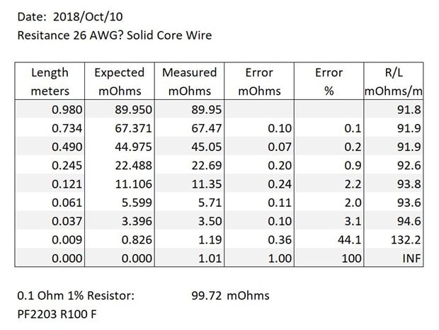
First observe the measurement of the 0.1 Ohm known resistor at the bottom of the table.  The measured 99.72 milliohms is within the tolerance of the resistor and very close to what I have measured in previous 4-wire tests using a bench power supply as the current source.  Now observe the table which is the measurements and calculations done on various lengths of the 26 AWG wire.  The first column is the measured length of the wire in meters.  The first value in the second column labeled Expected mOhms is the actual measured milliohms.  All the subsequent values are derived from it by calculating its value if it had exactly the same resistance per unit length as the first measurement.  The third column is the actual measured value on the bench multimeter.  The remaining columns are calculated values.


The fourth column, perhaps mislabeled as Error, is the difference between columns 2 and 3.  The fifth column is the calculated error assuming column 2 is correct.  And the 6th and last column is the calculated milliohms per meter for each piece of wire derived from the measured length and measurement from the multimeter.


I was surprised at how good the results are.  Even a 9 mm length of wire, expected to have a resistance of 0.8 milliohms, was measured to be 1.2 milliohms - only a 0.4 milliohm difference.  All other differences were less than or equal to 0.1 milliohm.  The final row with a length of 0 meters was obtained by clamping the probes to each other.  So, there is a roughly 1 millivolt (milliohm) offset from zero.


The biggest issue at the moment is extending the range.  It is currently 0 - 4 ohms and I would like to extend to at least 40 ohms and preferably 100 ohms or a bit more.  This could be done by reducing the current from the current source are reducing the gain.  Without a microcontroller to adjust or some additional circuitry this would mean the resistance would not be directly output in the same range as the output voltage however.  It is also slow to settle but eventually quite steady.


Next Steps

  • Add a LDO to the power section - probably 4.7V
  • Have a look at behavior on the scope
  • Add an on / off switch
  • Add LED to indicate status of power
  • Consider how to increase the range to at least 40 V
  • Make a decision on the output - bench meter, panel meter, or microcontroller with screen
  • Design a PCB and send for fabrication
  • Get a proper enclosure


Thanks for reading!  Comments and suggestions always appreciated.


Related Links

Even More on Current Sources and a Kelvin (4-Wire) Milliohm Meter

More on Current Sources and a Kelvin (4-Wire) Milliohm Meter

Testing Current Sources for a Kelvin (4-Wire) Milliohm Meter

  • Sign in to reply

Top Comments

  • jw0752
    jw0752 over 6 years ago +6
    Hi Frank, You have made an excellent approach to this project. I think the way the expected results correspond to the actual is very encouraging. For the fun of it the other night and inspired by your…
  • fmilburn
    fmilburn over 6 years ago in reply to jw0752 +6
    Additional note - I know you already understand this but when down in the single milliohm range all sorts of things start to matter. I am cleaning the connections to remove oxides on the wire, making sure…
  • shabaz
    shabaz over 6 years ago +5
    Hi Frank, This is great to see, it it excellent work on the schematics and the prototype! I hope you're planning to stick this as a Project14 entry : ) it definitely looks like a handy piece of test instrumentation…
  • fmilburn
    fmilburn over 6 years ago in reply to mcb1

    Hi Mark

    I agree - mostly being complimenting of John and Shabaz as I admire their projects.   I plan to get something together for Project14 but have a lot going on at the moment so if not instruments then analog.

    • Cancel
    • Vote Up +1 Vote Down
    • Sign in to reply
    • More
    • Cancel
  • mcb1
    mcb1 over 6 years ago in reply to fmilburn
    I have a personal goal to improve the build quality of my projects so if I can get this looking half as good as the stuff you and John Wiltrout turn out I will enter it.

    While I think your personal goal of improving the build quality is great, it shouldn't stop you from entering the Project14 challenges.


    The TM's had been advocating a challenge that had an entry level that could attract newer members, so having a slightly less 'polished' design is perfect for these Projects.

    Anyone wanting to emulate them will very likely produce their own housing and it might be whatever they can source.


    As long as the build detail is there, you should be considering entering it, as the cost is very low and the approach has always been something that achieves a high accuracy.

    Yes the design has issues above 4 ohms, but extending the range is available, or simply use it below 4 ohms.


    Mark

    • Cancel
    • Vote Up +1 Vote Down
    • Sign in to reply
    • More
    • Cancel
  • jw0752
    jw0752 over 6 years ago in reply to jw0752

    Anyone who may have copied the schematic that I published last night 6 posts up should disregard it as it had several problems. Here is a revised and hopefully correct replacement:


    image

    Tonight I redid my experiment to make a circuit that would keep a USB battery stimulated to supply power. In redoing the bread board using an NE555 timer, SN7414 inverting schmitt, and a 2N7000 MOSFET I discovered that some of the component values that I had used did not match my schematic. I also discovered that I had drawn pin 5 of the 555 to ground instead of placing a 10 nF cap to ground. I also made some modifications to the circuit specifications. I added a 270 ohm resistor at R4 to widen the pulse width of the trigger load for the USB Battery. The timing capacitors and resistors values have been changed to provide a pulse every 10 seconds. All in all it was a good idea to delete the bad schematic and repost it here. Here is a picture of the bread boarded revised circuit. I have also noted that the use of a NE 555 instead of the use of one section of a NE 556 has brought the quiescent circuit current down to 2.5 mA. Here are a couple more pictures:


    image

    Simplified bread board lay out

    image


    Circuit running a test


    John

    • Cancel
    • Vote Up +2 Vote Down
    • Sign in to reply
    • More
    • Cancel
  • fmilburn
    fmilburn over 6 years ago in reply to jw0752

    I just remembered it from somewhere I have forgotten. Which is not bad for me ;-)

    • Cancel
    • Vote Up +1 Vote Down
    • Sign in to reply
    • More
    • Cancel
  • jw0752
    jw0752 over 6 years ago in reply to fmilburn

    Hi Frank,

    I am going to spiff it up a little tonight and if it turns out I will post it separately with proper credit for the origin of my inspiration.

    John

    • Cancel
    • Vote Up +1 Vote Down
    • Sign in to reply
    • More
    • Cancel
>
element14 Community

element14 is the first online community specifically for engineers. Connect with your peers and get expert answers to your questions.

  • Members
  • Learn
  • Technologies
  • Challenges & Projects
  • Products
  • Store
  • About Us
  • Feedback & Support
  • FAQs
  • Terms of Use
  • Privacy Policy
  • Legal and Copyright Notices
  • Sitemap
  • Cookies

An Avnet Company © 2025 Premier Farnell Limited. All Rights Reserved.

Premier Farnell Ltd, registered in England and Wales (no 00876412), registered office: Farnell House, Forge Lane, Leeds LS12 2NE.

ICP 备案号 10220084.

Follow element14

  • X
  • Facebook
  • linkedin
  • YouTube