


In my earlier post Outdoor LED Lighting revival project , I focused mainly on the hanging LED lights. On this post I am looking more at the stair LED lights. Initially I had done a quick modification to my reflector design by enlarging the LED opening to accommodate not one LED, but now three LEDs. The change in design seemed a bit problematic as the LED opening started out as tube prior to opening up which might have focused the light more in the center of the lens. Thinking about this issue and the fact that most reflectors are parabolic in shape, I decide to try a different approach. Here is my initial reflector and my first attempt at an improved reflector:

While the new design would make fabrication of the foil reflector insert easier, the LED light path still has a tube-like opening. I was also worried that the lightpath to the edges of the reflector along the longer dimension would not be optimal. I then attempted to redesign the reflector by changing the direction of the elliptical trough. Here are the two new designs:

The two reflectors sort of remind me of bathroom fixtures, so I refer to them as the 'sink' (leftmost) and the 'tub' (rightmost). In reality what I really wanted is something more like a toilet, being more of a bowl shape, but I could not come up with a good bowl shape that meet other size requirements, so I decide to proceed with these two. The next step was to glue in foil liners to increase reflectivity.

Here are first the two foiled lined reflectors and the fully assembled reflectors (lenses snapped into the reflector frame). The foil I am using cones from a craft supply store and has an adhesive backing. I have had some trouble with getting the adhesive to hold the foil in place on the 3D printed reflector bodies, so I applied extra glue stick and carefully pressed the foil in place. In the 'tub' reflector, there is a pretty good reflection of the LED opening seen on the left-hand side of the reflector.
Next I wanted to test the illumination of the overall assembly, so I mounted my cellphone onto a support arm (old magnifier lens/helping hand base) and fixed the AE/AF lock (Auto Exposure and Auto Focus) on my iPhone so that the two pictures would have common exposure and image scales. The reflector under test is mounted opposite another reflector that is taped to the work surface, with the LED assembly mounted in between. Here is an image of be collecting an image:

After collecting the images of the two reflector in action, I loaded up my favorite image processing tool kit, ImageJ, and collected Histograms of the images.

The two Histograms are showing a huge peak one the black levels, that total wash out the bright details, so I offloaded the data into excel where I could manipulate the data more easily ('sink' -left, 'tub' -right). Here are the results from excel:

The blown-up images of the Histograms show that while both reflectors have a nearly identical high intensity count at ~ 188, the 'Sink' reflector has a much greater number of pixels in the 115 to 160 intensity range. Likewise, the 'Tub' has a much greater number of pixels in the 90 to 120 intensity range. Doing a simple calculation on the Histogram data, which is the sum of each intensity level (0-255) time the number of pixels at that level, I was able to see a >13% higher area/intensity value for the 'Sink' reflector.
Switching back to ImageJ, I converted the two images to Grayscale, 8-bit images and the used Image->Adjust->Threshold tool to graphically show where the bright/middle/dark regions of the image where. Due to the conversion to Grayscale the intensity levels don't exactly match the excel chart, but they do show an interesting view of the distribution of intensities of the two reflector assemblies (blue is below 128, grayscale is between 128 and 175 and green is above 175).
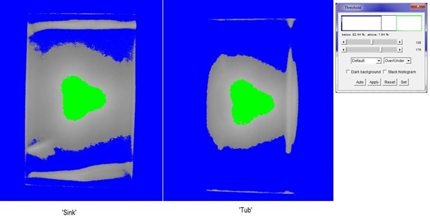
These images show again a nearly identical high intensity range (intensities above 175). The area of middle range of intensities is much larger in the 'Sink', although there are gaps and voids and some strange artifacts at the edges of the reflector. These artifacts might likely be due to more of the foil being present in beam angle of the LEDs. Given the beam angle (~120 degrees) and the relative short height of the reflectors (0.6"), there might not be very much light being reflected by the reflectors, although the difference in illumination patterns between the two reflector designs suggests that some light is being reflected.
At this point, based on some illumination Intensity data I had acquired in the prior post on various combinations of reflectors and lens combinations, I had decided to compare a naked reflector against a foil lined reflector to see if that added steps produced any significant changes in the intensity distributions. Again, use the setup above (but with a tighter/zoomed in view) I took images of the the foiled and un-foiled versions 'sink' reflector.

Here are the overall Histograms along with intensity plot profiles capture across the reflectors (the excel graph is the same plot profile data plotted on the same axis for a better comparison):

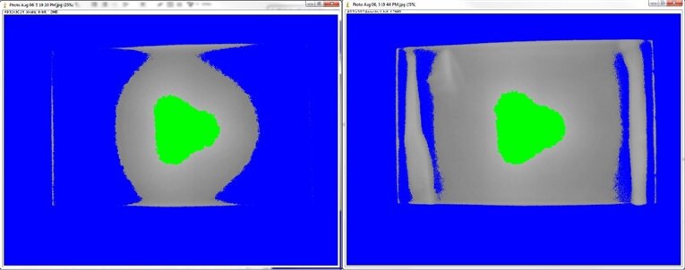

While the centers of the two reflectors had identical intensities, the intensities rolled off faster on the unlined reflector when moving away from the center. Repeating the same calculation on the Histogram data, which is the sum of each intensity level (0-255) time the number of pixels at that level, I was able to see a >21% higher area/intensity value for the 'Sink' reflector with the foil lining. Again the Threshold images clear show the intensity values across the reflectors (Oops, 1st image is no foil, 2nd image is foil lined).
With the process of lining the reflectors with foil taking a fair amount of time, and with me needing 8 of these reflectors for the two stair light fixtures, I want to see if I can make a unlined reflector that performs close to the foil lined reflector.
From here I am thinking about a couple of possibilities:
- Print reflectors in white PLA - In some intensity measurements white paper templates of the foil yielded similar or even higher intensities than the foil.
- Sand and paint the inside of the reflectors with a high reflectivity paint.
- Print reflectors in a high reflectivity PLA filament
I just started printing the white reflector so I will post more information as it becomes available.
Thanks for reading along!
Update 8/7/2021 2:30 PM
I just printed a reflector in white PLA and I am quite happy with the performance. Comparing the Foil, Gray and White reflectors, I see the following change in the results:

The thresholding of the white reflector shows an almost ideal distribution of intensity across the lens, without all of the edge effects seen on the foil lined reflector. Repeating my area/intensity value of the white reflector is >12% higher than that of the foil lined reflector. The resulting images and data leads me to believe that the white reflector with no other modification will be sufficient for my needs. So, no need to paint or purchase and new filaments at this time. All I need to do is print up another 7 of these reflectors and cut another 6 lenses.
Top Comments