In a prior blog ( Off the Shelf - Outdoor Lighting System Revamp ), I added outdoor lighting to my deck. Now I am extending the lighting from the deck, through the newly constructed path and garden (automatically controlled with the deck lighting). In late March, we started a project to remove another 200 sq. ft. of lawn in exchange for $200.00 worth of low-water native plants. The goal of the project was to construct a pathway connecting the deck to the garden (and shop), add more native plants to our yard and to build a recirculating water feature. The pathway was just screaming for some artsy LED lighting, so I jumped on that.
Here are some images of the path and garden under construction:


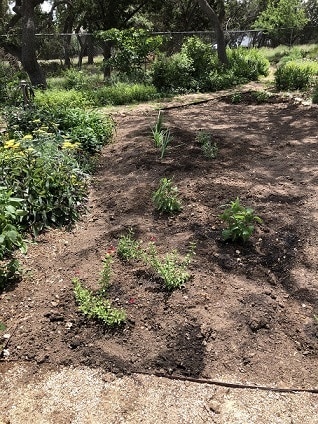
While there are still more plants that will need to be added to the garden, this marked the end of lawn removal project (for the rebate from the water company) and the start of the further improvement phase of the project.
My lighting plan is to add six path lights (three on each side of the path), staggered along the pathway. My wife is pitching in by adding her artistic touch of the glass blocks that will be used as the path lights. I am redesigning some of my prior LED lamps (like the ones that added to the deck in the above mentioned project). For this design, I wanted the LED light engine to do two things, one apply bright illumination on the edges of the glass block to light up the pathway, while secondly, applying a warmer, lower intensity lighting to the inside area of the block to allow the design to be seen at night. To achieve this effect, I used 6 LEDs, with 4 (cool white) LEDs mounted on one side of the PCB (to be pointed out) and 2 (warm white) LEDs mounted on the other side the PCB (to be pointed in).
Here are some of the details on the LED light engines:


The LEDs are individually constant current controlled, set for ~20 mA. With 12 LEDs per light fixture, the current draw is ~240 mA per fixture.
With a desire to control the light paths of the LEDs inside the blocks, I designed a reflector/board holder to mount the LEDs PCB. Here are some images of this design:

Telescoping rod parts:

Actual pieces, telescoping holding rods and LED holder/reflectors (Some of my finishes were less than spectacular due to the humidity, i.e. not fully dried filaments) .

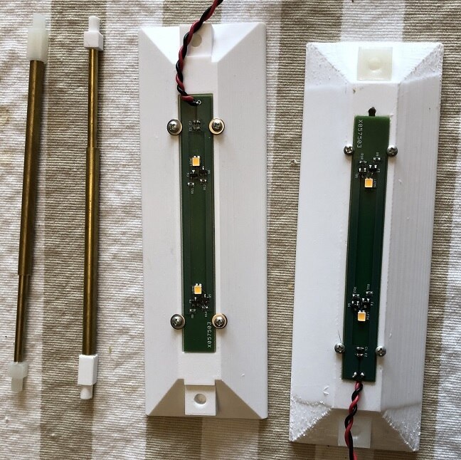
With the pieces assembled, the next step was to load up a glass block with the pieces. This proved to be quite difficult due to the limited opening of the glass block (~1.25" x 4.5").
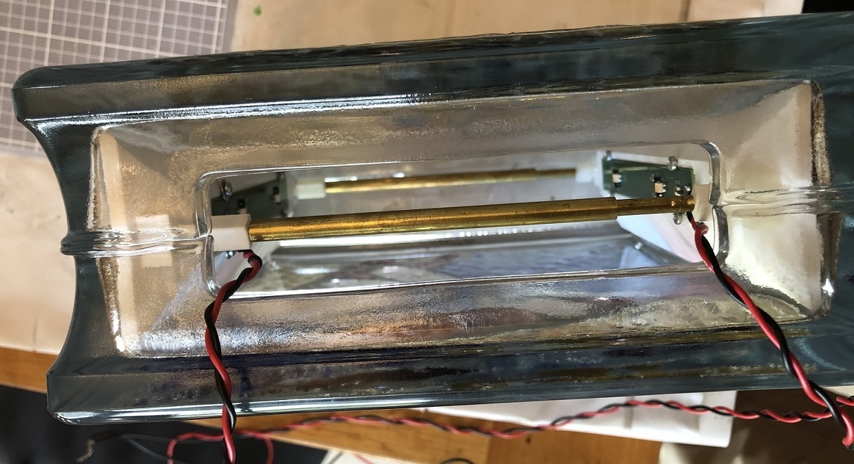
The two spring loaded, telescoping rods (brass tubing, with 3D printed ends and internal button inside the smaller diameter tube) are visible at the top and bottom of the glass block. The rods hold the reflectors snug up against the inner walls of the glass block.
Now with everything assembled, it was time to see how the lighting effects were on the completed (mosaics applied to the front and back of the glass block).


The lighting effects turned out really great. The images are visible and the edges are well illuminated. There is a bit of 'bright spotting' in the image, which might be improved with a diffuser, but I will wait until I get these installed to work on that. Now we have the first path marker ready, only 5 more to build.
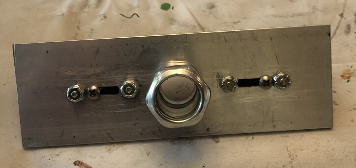
Mounting the glass blocks, was a tricky issue, but I think I have come up with an equally tricky solution. I want to elevate these blocks about a foot above then pathway, so I plan to use 1/2" EMT conduit as a post. I have designed a cover for the opening in the glass block (now at the bottom of the block), to cover the opening and provide a surface for a weather proofed closing and to mount the 1/2" EMT compression connector. I cut a 2" x 6" x 1/4" aluminum cover for the bottom. I then attached two blocks of HDPE (High Density Polyethylene) blocks to the cover that produced a snug fit to the opening. The HDPE was machine with a slot for movable tabs made out of 1/2" x 1/4" steel bar. The steel bar is retracted to insert the cover into the glass block and the extended to capture the edge of the glass block. The screw on the tab (secured by a 6-32 rivnut) is then tighten to secure the glass block to the base. Weather stripping will be applied to the cover and trapped between the cover and the block as the screws are tighten.
Here are some images of the cover assembly:

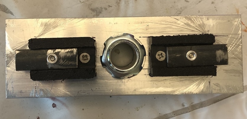

Again, all I need to do now is to repeat the process five more times and install everything. The 1/2" EMT conduit was be cast into concrete blocks, which will buried along side the pathway, with the lights staggered side-to-side.
I will follow up with another post as I get the pathway completed.
Thanks for reading along on my journey to light up my yard.
