element14 Community
element14 Community
    Register Log In
  • Site
  • Search
  • Log In Register
  • About Us
  • Community Hub
    Community Hub
    • What's New on element14
    • Feedback and Support
    • Benefits of Membership
    • Personal Blogs
    • Members Area
    • Achievement Levels
  • Learn
    Learn
    • Ask an Expert
    • eBooks
    • element14 presents
    • Learning Center
    • Tech Spotlight
    • STEM Academy
    • Webinars, Training and Events
    • Learning Groups
  • Technologies
    Technologies
    • 3D Printing
    • FPGA
    • Industrial Automation
    • Internet of Things
    • Power & Energy
    • Sensors
    • Technology Groups
  • Challenges & Projects
    Challenges & Projects
    • Design Challenges
    • element14 presents Projects
    • Project14
    • Arduino Projects
    • Raspberry Pi Projects
    • Project Groups
  • Products
    Products
    • Arduino
    • Avnet Boards Community
    • Dev Tools
    • Manufacturers
    • Multicomp Pro
    • Product Groups
    • Raspberry Pi
    • RoadTests & Reviews
  • Store
    Store
    • Visit Your Store
    • Choose another store...
      • Europe
      •  Austria (German)
      •  Belgium (Dutch, French)
      •  Bulgaria (Bulgarian)
      •  Czech Republic (Czech)
      •  Denmark (Danish)
      •  Estonia (Estonian)
      •  Finland (Finnish)
      •  France (French)
      •  Germany (German)
      •  Hungary (Hungarian)
      •  Ireland
      •  Israel
      •  Italy (Italian)
      •  Latvia (Latvian)
      •  
      •  Lithuania (Lithuanian)
      •  Netherlands (Dutch)
      •  Norway (Norwegian)
      •  Poland (Polish)
      •  Portugal (Portuguese)
      •  Romania (Romanian)
      •  Russia (Russian)
      •  Slovakia (Slovak)
      •  Slovenia (Slovenian)
      •  Spain (Spanish)
      •  Sweden (Swedish)
      •  Switzerland(German, French)
      •  Turkey (Turkish)
      •  United Kingdom
      • Asia Pacific
      •  Australia
      •  China
      •  Hong Kong
      •  India
      •  Korea (Korean)
      •  Malaysia
      •  New Zealand
      •  Philippines
      •  Singapore
      •  Taiwan
      •  Thailand (Thai)
      • Americas
      •  Brazil (Portuguese)
      •  Canada
      •  Mexico (Spanish)
      •  United States
      Can't find the country/region you're looking for? Visit our export site or find a local distributor.
  • Translate
  • Profile
  • Settings
Personal Blogs
  • Community Hub
  • More
Personal Blogs
Gene Breniman's Blog TC2-DSO review - SMT test adapters
  • Blog
  • Documents
  • Mentions
  • Sub-Groups
  • Tags
  • More
  • Cancel
  • New
  • Share
  • More
  • Cancel
Group Actions
  • Group RSS
  • More
  • Cancel
Engagement
  • Author Author: genebren
  • Date Created: 13 Jan 2023 5:17 PM Date Created
  • Views 1869 views
  • Likes 14 likes
  • Comments 10 comments
  • 3D Printing
  • SMT component testing
  • TC2-DSO
Related
Recommended

TC2-DSO review - SMT test adapters

genebren
genebren
13 Jan 2023

In my prior blogs (  Post Christmas shopping find - TC2-DSO review.and  TC2-DSO review - Continued  ) I tested several leaded component with the TC2-DSO meter.  This is all well and good, but I do not use many (if any) leaded components in my products/projects, so I really wanted to come up with a way to test components that I might actually use.  Here is a design for testing 0603 and SOT-23 analog components.

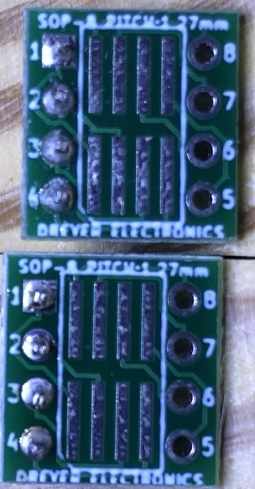
I thought that a great starting point for a 0603 and SOT-23 device adapter would be some SOIC adapters that I have used in the past.  With a single 4-pin header attached on one side I would have more than enough contact points for the TC2 meter. The adapter has two usable sides, one with 0.05" spaced pads, the other with 0.025" spaced pads.  The 0.05" pad spacing is almost ideal for the 0603 and SOT-23 footprints.

image

Next I designed some SMT chip holders in Fusion360 to hold and align the devices to the SOIC adapter board.  Here is what I came up with:

imageimageimage

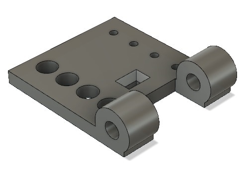
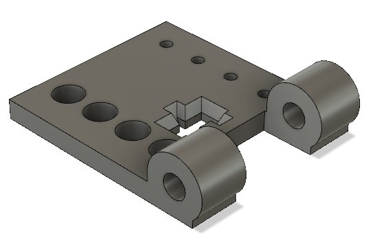
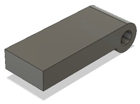
The parts are designed with four clearance holes on one side (to align with the header solder to the SIOC adapter board, a four alignment holes that will provide a tight fit with another header the will pass through the SIOC adapter board and into the component holders.  The two designs have different component outlines, with chamfers added to guide the components into the part outlines.  A flip lid can be attached to either/both bases, with a 1/2" long 0/80 screw (thread tight on the base and oversized on the lid.  Using a small rubber pad on top of the device should allow sufficient pressure to achieve good lead contact to the SIOC adapter board pads.

Next I printed the component holder parts and tried everything out.  Now here is were I admit that it took three design iterations to get the fit and function that I was hoping for.  Even with the multiple passes, I feel that the component holder parts were requiring a higher accuracy that my printer could provide, so the parts required quite a bit of cleanup to work.  Maybe in the future I might need to get extruder tips with much finer holes for my printer.  Here are the printed (and cleaned up) parts mounted on the SOIC adapter boards.

imageimage

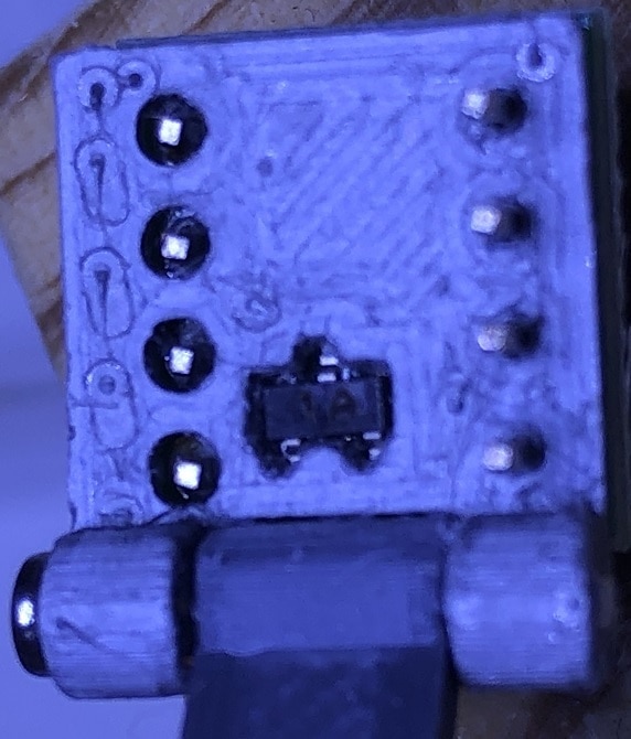
Next to test the component holders I inserted some SMT components into the holder openings, starting with the 0603 adapter (the rubber pad here was a small piece of a rubber band).

imageimage

Flipping the lid and pressing it closed with my finger, the component made good contact and the TC2 was able to properly read the component value

image

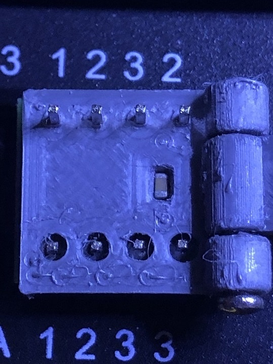
Next I tested the SOT-23 component holder.

imageimage

Flipping the lid and pressing it closed with my finger, the component made good contact and the TC2 was able to properly read the component value

image

There still a lot of room for improvement, but for the moment I think that I have achieved my goal.

Thanks for reading along

Thanks for reading along!

  • Sign in to reply
  • genebren
    genebren over 2 years ago in reply to Andrew J

    A 3D printer can be both the best and the worst thing.  I love being able to create a wide variety of parts, but sometimes the getting the printer to work flawlessly is a real problem.  There are a lot of things that have to go right (like filament dryness, bed adhesion, temperature, etc) to get your part to come out right. Don't get me wrong, I am glad that I pulled the trigger and bought one.

    Actually, this is my second printer (PRUSA). I had a Monoprice Maker Select that was very difficult to get good results with, until it fried the motherboard.  I good printer makes the difference.

    • Cancel
    • Vote Up 0 Vote Down
    • Sign in to reply
    • More
    • Cancel
  • Andrew J
    Andrew J over 2 years ago

    Neat idea.  I must look into getting a 3D printer.

    • Cancel
    • Vote Up 0 Vote Down
    • Sign in to reply
    • More
    • Cancel
  • DAB
    DAB over 2 years ago

    Cool build, well done.

    • Cancel
    • Vote Up 0 Vote Down
    • Sign in to reply
    • More
    • Cancel
  • genebren
    genebren over 2 years ago in reply to shabaz

    Thanks shabaz !

    I do like your un-3D-printer concept.  I was sort of going down a similar path. Here is an image of the components on the adapter board:

    image

    I was thinking that you could add small wires (red lines)  to act as guides to align the components onto the pads, sort of like this:

    image

    Or even something like small pieces of brass/copper channel, soldered to the adapter board.  I guess you could even use small pieces of FR4 and glue them on the edges of the component outline.

    But do think that it would be very hard to beat the accuracy and low cost of a PCB manufactured approach.

    It is so nice to share ideas with sharp minds!

    • Cancel
    • Vote Up 0 Vote Down
    • Sign in to reply
    • More
    • Cancel
  • shabaz
    shabaz over 2 years ago

    Hi Gene,

    Nice work!

    It meets a real need, how to conveniently attach to such discrete components for easy measurement/testing. 

    I was thinking how to un-3D-printer your idea (because I don't have a 3D printer hehe), and couldn't think of a way, but did come up with a hybrid idea that you may be interested in. It's still a bit of a half baked idea:

    What if the component shape was cut out of PCB material, by the PCB manufacturer? That's not too hard, since they can cut shapes. Then, there could either be lots of them, so they could be swapped in and out of your 3D printed hinge mechanism, or alternatively, it could be a single (say) 100x100mm board with a load of shapes cut out, and then a single PCB underneath that with the pads in the right places. It leaves the matter of how to apply pressure to the component, that could be with a 3D printed plate with tiny bumps on the right places perhaps (and aligment pegs to fit it correctly of course).

    • Cancel
    • Vote Up 0 Vote Down
    • Sign in to reply
    • More
    • Cancel
>
element14 Community

element14 is the first online community specifically for engineers. Connect with your peers and get expert answers to your questions.

  • Members
  • Learn
  • Technologies
  • Challenges & Projects
  • Products
  • Store
  • About Us
  • Feedback & Support
  • FAQs
  • Terms of Use
  • Privacy Policy
  • Legal and Copyright Notices
  • Sitemap
  • Cookies

An Avnet Company © 2025 Premier Farnell Limited. All Rights Reserved.

Premier Farnell Ltd, registered in England and Wales (no 00876412), registered office: Farnell House, Forge Lane, Leeds LS12 2NE.

ICP 备案号 10220084.

Follow element14

  • X
  • Facebook
  • linkedin
  • YouTube