


In this chapter, I will be looking at the various remote interfaces and PC connectivity options, including their latest Test Bridge software which was still in Beta/Release Candidate stage of development at the time of review.
PC Connectivity
The Aim-TTi QPX750SP offers USB and Ethernet (LAN-LXI) as standard with GPIB available as an option. Unlike other models in the line-up, RS-232 (Serial) is not offered.
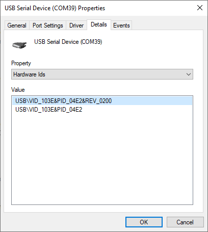
The philosophy of the QPX750SP seems to be to keep things simple. As a result, the USB connectivity offered is only as USB-CDC so that the instrument appears as a serial port, rather than the more customary USB-TMC which is reserved only for test instruments. This may make it easier to implement and more compatible with applications as a full-fledged VISA is not required. It does eschew some potential benefits of USB-TMC in emulating GPIB asynchronous lines, but this does not really have any material impact on a device where synchronization or high speeds is not required. Testing it on a Windows 10 machine did not require the installation of any drivers and it was detected by NI-VISA just fine. Testing it on a Linux machine also did not require any special configuration. Drivers are provided for older versions of Windows.

Over LAN, the unit is reachable by a web browser as required by the LXI standard. A fairly basic interface is provided to identify the instrument and its settings.
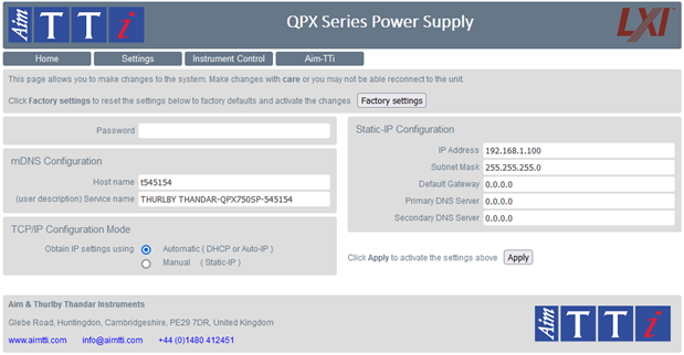
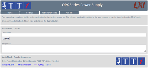
Sending SCPI commands and changing the LAN settings are also available via the web interface. A password can also be set for security, which can be restored to default using a reset of LAN settings on the instrument.
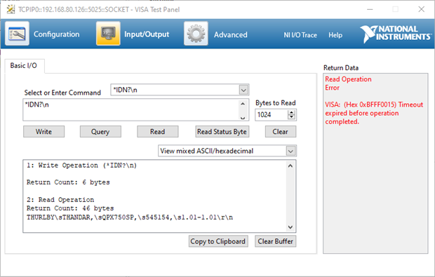
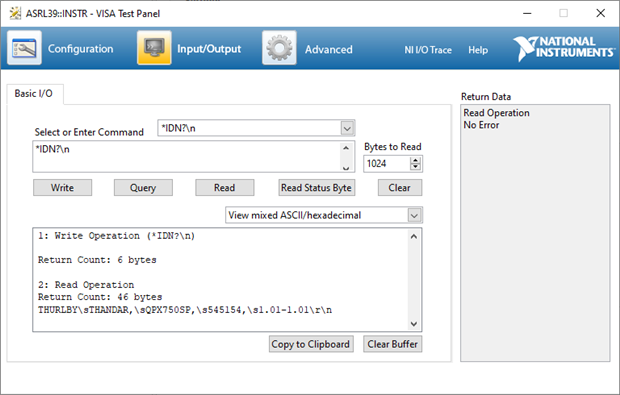
The instrument was also tested just fine using NI-VISA, although it implements just a TCP/IP socket interface for simplicity, rather than the full VXI-11 protocol which they consider “legacy” but is still quite relevant. This has similar disadvantages with regards to emulation of GPIB asynchronous lines, but again, is not entirely relevant to a general-purpose power supply. The advantage is that it can be interfaced with directly using any program that can communicate with a TCP/IP socket and does not require a full VISA stack.
One issue with the implementation appears to be that the instrument becomes unreachable if a program does not terminate correctly. I mentioned this to Aim-TTi which identified the problem as the instrument only having a single socket, thus if a connection is hung open, the instrument will not accept any other connection attempt. They have mentioned they are looking into making it capable of multi-socket operation to alleviate this potential issue.
Scanning of open ports reveals that the unit really has the “bare bones” minimum with just HTTP 1.0 on its embedded web server, but also that it implements the “echo” protocol which is uncommon to see nowadays as it is a legacy protocol.
PORT STATE SERVICE VERSION
7/tcp open echo
7/udp open echo
68/udp open|filtered dhcpc
80/tcp open http Oryx Embedded HTTP Server
| fingerprint-strings:
| GetRequest, HTTPOptions:
| HTTP/1.0 200 OK
| Server: Oryx Embedded HTTP Server
| Connection: close
| Content-Type: text/html
| <!DOCTYPE html>
| <html lang="en">
| <head>
| <meta http-equiv="Content-Type" content="text/html; charset=utf-8">
| <link type="text/css" rel="stylesheet" href="css/stylemain.css" title="CSS">
| <link type="image/favicon" rel="shortcut icon" href="favicon.ico?v=1">
| <title>QPX Series</title>
| <script src="/js/home_identify.js"></script>
| </head>
| <body id = "home">
| <div>
| <div>
| title = "Visit the Aim-TTi website" target="_blank" href="https://www.aimtti.com" ><img class = "logo" src = "images/AimTTiLogo.png" alt = "Aim-TTi Logo"></a>
| <img class = "lxi-logo" src = "images/LXILogo.png" alt = "LXI Logo">
| <div class = "title">
| <h1>QPX Series Power Supply</h1>
| </div>
| </div><!-- header -->
|_ <div>
|_http-server-header: Oryx Embedded HTTP Server
137/udp open|filtered netbios-ns
5025/tcp open tcpwrapped
5353/udp open zeroconf?
| fingerprint-strings:
| DNS-SD:
| _services
| _dns-sd
| _udp
| local
| _http
| _tcp
| local
| _services
| _dns-sd
| _udp
| local
| _lxi
| _tcp
| local
| _services
| _dns-sd
| _udp
| local
| _scpi-raw
| _tcp
|_ local
Remote Control Benchmark - scpibenchv1
Something that I was interested in knowing is just how quickly the QPX750SP can respond to SCPI remote control requests. As this is something I’ve always wanted to test across instruments, I went looking for a decent benchmark but found none. As a result, I decided to write my own and did some testing on my suite of instruments on my own personal blog.
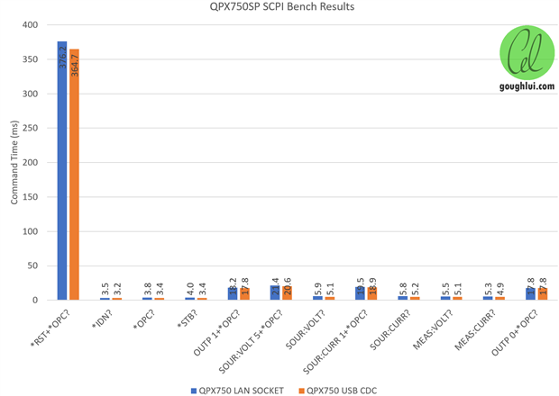
On the whole, it seems the QPX750SP is no slouch with most simple requests being completed in 3-4ms, measurements taking around 5ms and commands involving changes taking about 17-22ms. The time taken for a reset, however, is noticeably longer at about 360-380ms. This should still be amply fast given the speed of the metering of the unit is much slower than this.
Quasi-Analog Control & Monitoring
The quasi-analog control feature allows for an analog voltage input to control the voltage and/or the current output of the power supply. The input voltage can be selected as 0 to 5V or 0 to 10V full-scale and is periodically sampled by the power supply. To test its accuracy, I generated input from a Keithley 2450 SourceMeter at 50µV steps across all combinations of settings and measured the set-point that the QPX750SP would deliver as a result of the analog input.

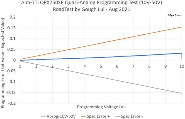
Programming of voltage in the 50V range showed the analog control input to be well within specifications, deviating a maximum of about 40mV from the expected output voltage.
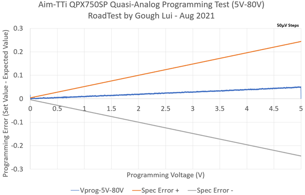
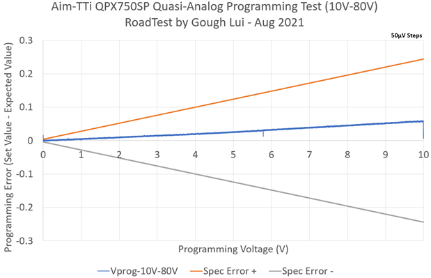
Repeating for voltage in the 80V range, the result was well within the promised specifications reaching a maximum of about 60mV deviation from the expected value.

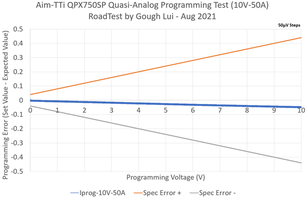
Errors with current programming appeared to be opposite in sign compared to the voltage, although the result is also well within bounds, peaking at about 50mA deviation when the granularity of current programming is considered. It seems the accuracy of quasi-analog control is quite good.
I also tested the response of the quasi-analog control and the current/voltage monitoring outputs briefly by using my Rohde & Schwarz RTM3004 to generate a signal into the current control line and monitoring the outputs of the monitoring lines versus a Holdpeak HP-605C inductive clamp meter.
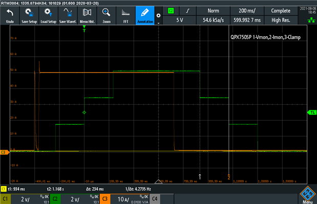
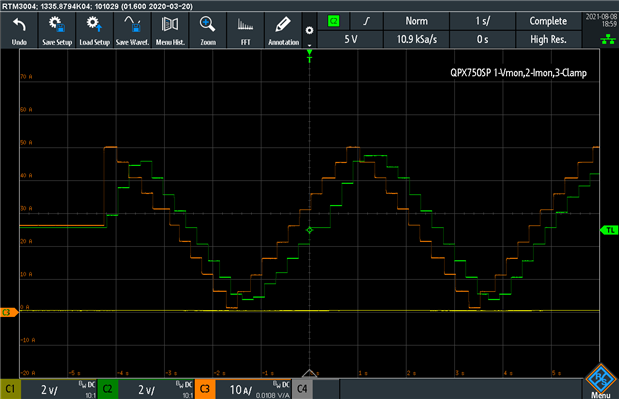
The temporal behaviour of the quasi-analog monitoring can be seen – the clamp meter in the left figure shows the result of powering up into a dead short. The power supply comes on, has a hiccup, then enters into constant current at 50A. The quasi-analog monitoring lags behind the actual current output by about 400ms, and seems to be “smoothed” resulting in a staircase pattern for what is essentially a current step. The update frequency is approximately 4Hz, as expected.
Being fed a sawtooth waveform from the signal generator, the actual power supply current output can be seen to be varied in steps as measured by the clamp meter, with the monitor output lagging behind as before. While quasi-analog control and monitoring are accurate beyond the datasheet’s specifications, the limitations of its sampled nature should be considered by integrators looking to use these features.
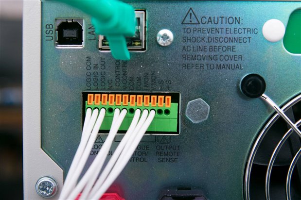
Digital Logic I/O
In addition to the quasi-analog control and monitoring, a digital logic input and output are provided which can be used to turn the channel on or off, and monitor whether the output is on, tripped or in a given mode. The logic input is isolated and can accept a voltage of about 3.3V or greater to assert the input, while the output is essentially open-collector, requiring a pull-up in case you wish to turn it into a voltage.
To test this, I put in a simple square wave from the RTM3004 into the logic in and pulled the logic out high using a Rohde & Schwarz NGU401 SMU. Because of the fast transitions from pulled-down to open, the SMU overshoots resulting in some clipping in the graph, but this is unimportant for this test. The plot was configured for repeat triggering and infinite persistence.
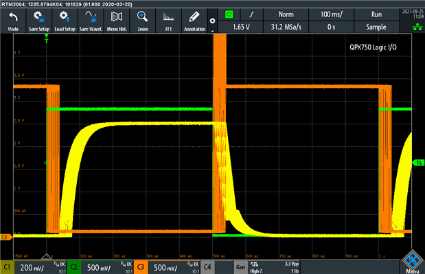
The input is shown in green, with the output voltage in yellow. Turning the output on results in the logic output for the channel in orange reflecting the state change within about 40ms. The output doesn’t actually start until another 40ms or so have elapsed. Turning the output off, however, took anywhere from zero up to 40ms to reflect on the logic output and the voltage output followed almost perfectly in sync. It seems easier to turn off a channel than it is to turn it on, so some duty-cycle distortion is to be expected from using digital logic I/O control to toggle the channel output. The manual and datasheet gives no guidance as to response times, so the measured values may only apply to this particular testing scenario.
Test Bridge (Beta & RC2)
It seems popular for instrument vendors to bundle some software to help users get started quickly and Aim-TTi’s offering is called Test Bridge. During the course of this review, I tested Beta 7 and 10 and the Release Candidate 2 along with early-stage documentation. Just like Aim-TTi’s other documentation, it seemed a bit brief but easy to read with a lot of useful information to help users get started. This section will contain screenshots from a mix of versions, as most of the changes seemingly occurred under-the-hood.
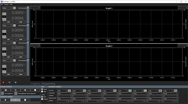
On first impression, the software has a dark theme similar to some of Keysight’s software offerings, and seems a bit cluttered with the four instrument panels (each potentially with multiple channels) and two graphs on display. There is a lot of flexibility in terms of defining the axes and assigning them to plots, however, it seems the clutter of the screen arrangement is non-negotiable and does not render well if you have a screen resolution less than 1920x1080. The application seems to be using .NET and does not require the installation of a VISA stack which is slightly uncommon amongst such software but also is a great advantage as it means a smaller installation size and no VISA conflicts.
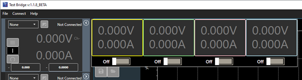
The instrument panel view is shown by default, but there are also views for communications between the instrument and the error log. Refresh interval can also be changed – it defaults to 1s but can be dialled down to 0.1s if desired. Values in the graph can be sampled down to 0.25s for the QPX750SP. It seems that custom/abbreviated SCPI commands are used for communications between the instrument and Test Bridge. Multi-channel instruments can have the side bar expanded to show the state of each instrument, with the software currently supporting power supplies in the CPX, MX, PL, QL, QPX and TSX series and loads in the LD and LDH series.
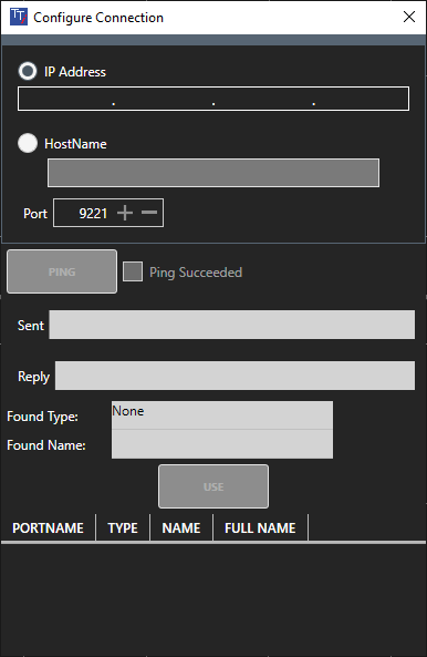
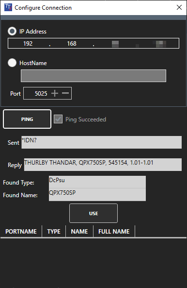
To get started with an instrument, it must be configured in the connections. The default port number does not appear to be valid for the QPX750SP, so it must be manually changed to SCPI-Direct on 5025 and then added to the list using the “use” button. Once connected, the status is shown on the side bar.
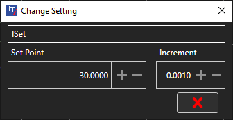
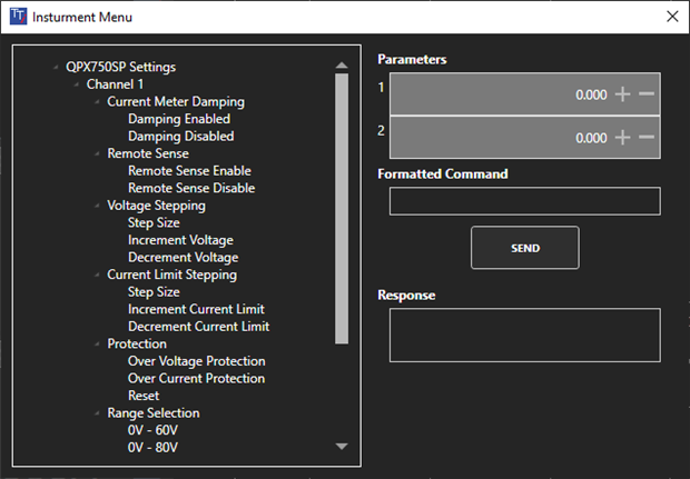
Settings for current or voltage can be changed directly in the boxes and more sophisticated commands can be issued from a tree of commands, eliminating the need to consult the manual, which is a great convenience.

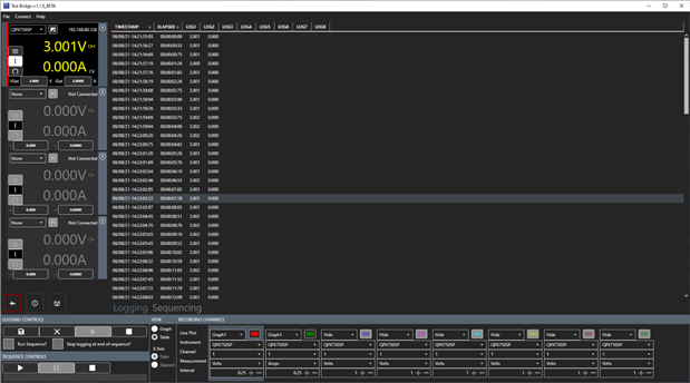
While the default view is the graph view, a table view is also provided if desired, with the X-axis switchable from labelling based on date and time to elapsed time. The above graph is the result of running a sequence with the software.
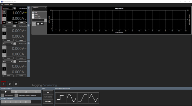

The sequence feature allows you to build a waveform for either volts or amps, potentially triggered on an event, made of blocks that involve a step, sine, ramp or sawtooth components. Each component is configured for the necessary parameters and can be chained with multiple blocks to produce more complicated waveforms, subject to the limitations of your equipment. In the case of me trying to slew the current too quickly using the waveform feature, I was able to provoke an instrument fault.
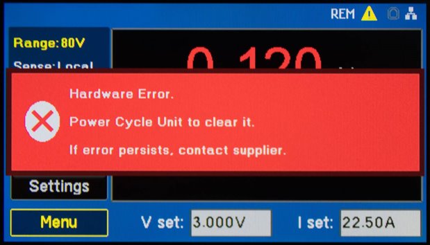
This has been reported to Aim-TTi and the cause has been identified. A rectification for this issue has been promised in an upcoming firmware revision.
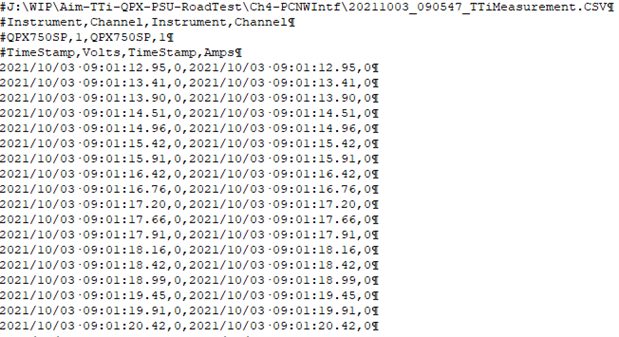
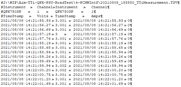
Test Bridge also supports the logging of data, with or without a running sequence, which can be exported as CSV, TSV or text (which appears to also be TSV).
While I did not use Test Bridge much for the purposes of this review, as it was more flexible to use the instrument directly through my own pyvisa scripts, the Test Bridge software does add significant value to those who may not be able or willing to program their own software and just want a quick remote-panel with logging or waveform generation features. It does, to some extent, help with the lack of a USB host port on the instrument itself and the lack of onboard logging or sequencing functionality. However, as this requires a computer to be powered on and running, and it incurs a performance penalty due to the communication overhead, this is not a perfect solution. It also seems to only be available for Microsoft Windows operating systems, so that could also be potentially a problem for some users. I do feel that the interface feels a bit too cluttered by default, and I would have appreciated the ability to hide unused graphs and non-connected instruments in the side panel for the possibility for a larger virtual front-panel display. But on the whole, it was easy to get acquainted with and it seemed to work as expected for the limited amount of testing I performed.
Conclusion
The Aim-TTi QPX750SP comes with USB and Ethernet (LAN-LXI) connectivity by default, with GPIB available as an option. Unlike other members of the QPX family, RS-232RS-232 Serial is not available. The USB connection is enumerated as a CDC virtual serial port, requiring no drivers on modern operating systems. This is not the customary USB-TMC that may be expected from test instruments, but the choice of CDC does lead to wider compatibility and ease of use in non-VISA environments. The downside of not being able to emulate GPIB asynchronous lines is perhaps not a big issue for an instrument like a general-purpose power supply. The LAN interface is seemingly similar, supporting only SOCKET connectivity rather than VXI-11 with similar drawbacks and advantages. The web interface is also relatively spartan, offering remote command and settings change functionality only.
Tests involving the SCPI remote control proved to be reliable over long test sequences, although the single-socket implementation can leave the instrument in an un-connectable state with a hung open TCP socket connection in case a program is improperly terminated. This has been reported to Aim-TTi who are investigating a revision to improve this through implementing multiple sockets. Response times on SCPI remote control were generally very fast, with simple queries clocking in at 3-4ms, measurements around 6ms and commands involving changes reaching 17-22ms. The reset operation took quite a bit longer at about 360-380ms.
Quasi-analog control and monitoring is offered and tests of the accuracy using the Keithley 2450 SourceMeter as input showed that the unit was accurately digitising the input with a deviations much smaller than implied by manual specifications. At a 50V range, maximum programming error was about 40mV; at 80V range, maximum programming error was about 60mV; and at 50A range, maximum programming error reached 50mA. In all cases, the offsets were dominated by gain-error. Unfortunately, the quasi-analog sampled nature of the input appears to operate at about 4Hz and results in some lag with the monitoring output reflecting changes with a delay around 400ms. Because of this, use of the quasi-analog control to generate waveforms with rapid changes will result in a stair-step output rather than a smooth change.
Optoisolated digital logic input and output is also available, with testing showing that a logic input is reflected to the logic output within about 40ms. Channel switch-on seems to require another 40ms, although turning channels off were much more in-sync with everything completed within about 40ms. If this mechanism is used to generate pulse waves, this discrepancy may cause some duty-cycle distortion, but otherwise, it seems relatively quick compared to the analog control.
The Test Bridge software is not yet in its final release state, but as it stands, it offers quite a bit of value for new users who may not want or are not able to program their own software. It offers functionality including remote operation, configuration, sequencing, charting and data logging. It is free-of-charge and goes in some way to ameliorating the fact that the QPX750SP has no onboard logging, sequencing or USB host functionalities. The software is fairly easy to use once the cluttered interface is mastered and is capable of supporting multiple instruments from Aim-TTi as your needs grow. Unfortunately, it seems to only be available for Microsoft Windows operating systems and renders poorly on displays smaller than 1920 x 1080 resolution. While the sequencing function is very enticing, its capabilities are limited by both instrument capabilities and communication overhead.
---
This chapter is a part of the Aim-TTi QPX750SP 750W PowerFlex Programmable DC Power Supply RoadTest Review. More detailed chapters are linked from within the main review.