


As the QPX750SP has an extended voltage range capability that reaches 80V, a key application would be to test telecommunications-based equipment which may be 48V nominal, but require voltages up to 60V to properly test. Initially, I thought I would test some 48V DC-to-DC modules, but having tested them before, their low power rating was perhaps problematic. As a result, I decided that I would try to measure the efficiency of the Microchip PoE-to-USB-C PD Adapter that I recently RoadTested. Unfortunately, as PoE requires proper negotiation, this posed a bit of a challenge which required some creativity to solve. As a bonus, I also saw a rather lonely 10A circuit breaker on my desk for another project and thought it would be fun to test that with the QPX750SP as well.
Microchip PoE to USB-C PD Adapter Efficiency Measurement
The Microchip PoE-to-USB-C PD Adapter is an 802.3bt PoE device which requires a four-wire mode 90W injector to achieve its full performance. I made some end-to-end efficiency measurements in that review but those figures are (obviously) dependent on the power injector’s intrinsic efficiency. Unfortunately, the only 802.3bt injector I had available to me was a DSLKIT BTIN5219 which was simple but also had rather lousy efficiency.
Wanting a more accurate figure on the efficiency of the PoE-to-USB-C adapter, I decided that I would take the “knife” to the rather pricey injector to make it into a one-of-a-kind device.
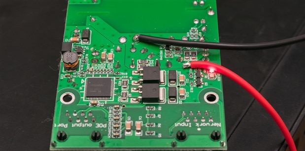

By tracing out the circuit, I attached wires to the output capacitor that follows the synchronous rectifier MOSFET so that I could inject power into the PoE controller directly. This way, I can preserve the negotiation and switching logic while cutting out the AC-to-DC converter on this injector. I terminated the silicone wire in some crimps and drilled some holes into the casing to mount two banana sockets. This would allow for applying DC power externally, or for use as a power supply.
This was not a perfect solution, of course. For one, the negotiation circuitry consumes current and so do the status LEDs which would have to be measured and subtracted to improve accuracy. Another issue is the fact that the unit natively puts out about 51.5V when it should be 52-57V by specification. This makes me very hesitant to apply more than 52V to the unit as I suspect the internal switching regulator will probably be trying to down-regulate the output. Their choice of 63V capacitors on the output doesn’t offer much margin either.
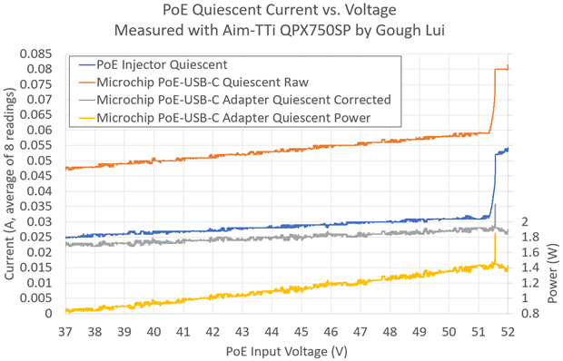
The first step was to measure the quiescent current of the negotiation circuitry alone without any peer connected. This was done by a pyvisa script which swept the voltage from 52V down to 37V in 2mV steps, taking the average of eight readings to improve accuracy as the QPX750SP’s current resolution is relatively limited. Despite this, I didn’t want to use an external DMM as I did last time, so the QPX750SP has its chance to shine. In spite of its 10mA display granularity, the readout over SCPI seems to be a bit more granular at 1mA for readings below 1A and when averaged, isn’t too bad at all. The result is shown in blue and shows a steep rise around 51.5V, even though the current is still relatively tame, I didn’t want to risk it.
I repeated this with the PoE-USB-C PD adapter attached to the injector with no load. The raw result is shown in orange and is corrected by removing the baseline quiescent current reading in grey. The small “spike” is probably due to a slight mismatch in the steep portion of the curve and is unlikely to represent a real reading. The result suggests the quiescent current of the adapter is about 23-28mA for a quiescent power between about 0.8-1.5W which is not insignificant.
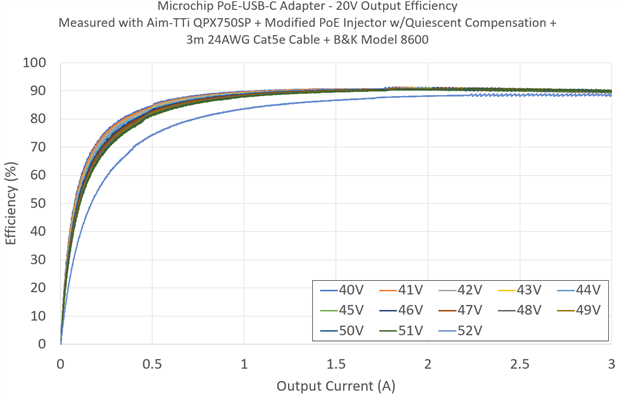
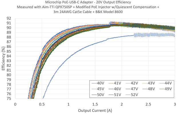
Automating a script that steps the voltage into the injector from 40 to 52V in 1V steps, I swept the load using a B&K Precision Model 8600 DC Electronic Load and USB-C PD Decoy Board. Taking the readings and computing the efficiency while correcting for baseline quiescent current, I could draw the following efficiency plot. It is still not perfect as it includes losses in the 3m Cat5e cable and some losses in the USB-C cable which has an LED and is not corrected for the self-consumption of the decoy board (which I could have done as it has been characterised), however, it is much more representative of the efficiency than my earlier attempts.
In this case, it seems the 52V reading is anomalously low, possibly because of differences in baseline quiescent current that could depend on other factors (e.g. temperature) and I think it is best to ignore it. All the other readings are fairly similar, showing peak efficiency around 90.8% and oscillations at higher current/power levels due to the QPX750SP’s 10mA current granularity above 1A. It manages to reach 75% efficiency by a load of about 400mA at 20V (8W).
Bonus: Testing a 10A Circuit Breaker
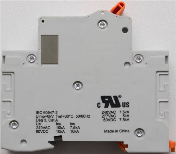
This one is a bit of a bonus and was the result of some spur-of-the-moment thinking. I had this Weidmuller SU1C10UC C-curve circuit breaker (Order Number 2824831) on my desk for another project and I’ve always wondered just how good it was.
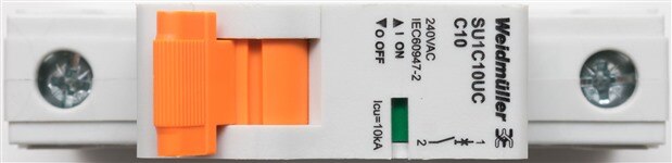
I know you could just look up the characteristic curves in the datasheet, but I wanted to know what that meant in practice, so I decided I would try sending through various currents and measuring the time it takes to trip using my Rohde and Schwarz RTM3004 oscilloscope. I repeated the test at each current level several times, waiting random amounts of time but not shorter than about 30 seconds.
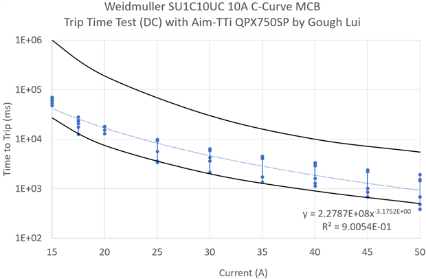
As expected, it was a bit of a mix of results because of the issue of accumulated heat within the circuit breaker over consecutive trips. The unit did behave as expected, the fitted line fitting in-between the two black lines which represent the envelope of trip times for a C-curve breaker. Some individual readings did touch or cross the line briefly – this is likely due to accumulated heat. At least I did satisfy my curiosity in testing whether the breaker works – it does, and even at a current of 50A, it would take about 1s to trip.
Bonus: Gratuitous Component Destruction
One benefit of having a big power supply is being able to put big voltages and currents through things that probably shouldn’t have big voltages and currents going through it. This is some destruction done deliberately, in the name of science of course.
For example, I’ve heard that MOVs can “let go” in a rather violent manner and I had some 35V (AC) or 45V (DC) rated MOVs that require 60V+ to really get into clamping … the QPX750SP seems to fit the bill rather well. Perhaps trying a few diodes, LEDs and resistors won’t go astray either.
So here is a bonus video, in slow-motion, of what happens when you decide to deliberately let out the magic smoke:
Conclusion
The extended voltage range of the QPX750SP can be quite useful for those who need to test telecommunications-based equipment which may be rated at 48V nominal, as they may need to operate close to 60V under extreme conditions.
To demonstrate this and allow the QPX750SP a chance to show its internal metering capability, a creative approach was taken to measure the efficiency of the Microchip PoE-to-USB-C PD Adapter that was recently RoadTested. By modifying the 802.3bt power injector, it was possible to retain the output negotiation logic while feeding your own “48V nominal” supply. Taking baseline readings to compensate for this circuit’s quiescent consumption, it was possible to measure the quiescent consumption of the adapter to be about 0.8-1.5W depending on voltage. Testing the unit under USB-C PD 20V/60W capable load created using a B&K Precision Model 8600 DC Electronic Load and a USB-C PD Decoy Board demonstrated peak efficiency of about 90.8% which is pretty impressive, with 75% efficiency being attained by a load of 8W. This is inclusive of the power loss in 3m of 24AWG Cat5e cable and quiescent loss in the decoy board and USB-C cable losses. The actual efficiency is probably a little higher, but the QPX750SP’s capability to source higher voltages and meter down to 1mA below 1A via SCPI was instrumental to obtaining such good results.
A spur-of-the-moment experiment had me measuring the trip times for a Weidmuller SU1C10UC C-curve circuit breaker by using the QPX750SP to source a range of currents up to 50A. By measuring times with an oscilloscope, it was possible to confirm the breaker was behaving as specified. I was also able to make use of the voltage and current capabilities to do some magic smoke liberation experiments in the name of science.
---
This chapter is a part of the Aim-TTi QPX750SP 750W PowerFlex Programmable DC Power Supply RoadTest Review. More detailed chapters are linked from within the main review.
-

DAB
-
Cancel
-
Vote Up
0
Vote Down
-
-
Sign in to reply
-
More
-
Cancel
Comment-

DAB
-
Cancel
-
Vote Up
0
Vote Down
-
-
Sign in to reply
-
More
-
Cancel
Children