


It’s been a great journey reviewing the Aim-TTi QPX750SP 750W Programmable DC Power Supply so far, but wouldn’t it be nice to end it all with a peek under the covers? After all, I don’t see any warranty void seals and the fuse is inside the cover, so I suppose it couldn’t hurt …
Peeking Under the Covers
Removing just two screws on the back allows for the top cover to come off, which is nice and convenient.
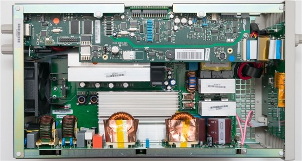
My first impressions are that of amazement – they have really packed more into the chassis than I would have expected. Not only is there a main PCB on the bottom, but vertical PCBs on the side and a control PCB which sticks out like a mezzanine. Another PCB handles the front panel and display, while heatsinks all “jostle” for space in the remaining gaps. It’s tight enough that I’m not going to do a proper teardown, just in case I break something, so I’m just going to focus on the boards that I can see without any further disassembly.
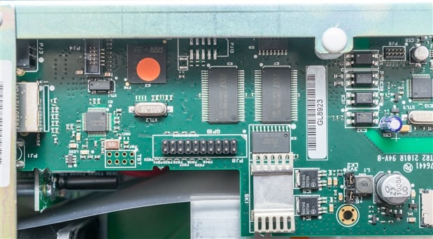
The first board I will be looking closely at is the control board which appears to be common with the QPX1500 as well. This board seems to house the brains of the supply. Major components on the first image include the National Semiconductor DP83848 PHYTER Ethernet PHY, an ST Microelectronics STM32F429 180MHz ARM Cortex-M4 Microcontroller, two ISSI IS62WV25616BLL-55TLIIS62WV25616BLL-55TLI 4Mbit SRAM, an IDT QS3245 8-bit CMOS Bus Switch, four Vishay SFH615A Optoisolators and two On Semiconductor NCP5661 LDOs. There are jumpers that seem to enable/disable these LDOs and a header where the GPIB option would attach.
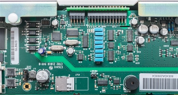
The second image looks towards the middle of the board where isolation can clearly be seen cutting across the board. Key components identified include a Transcend 300S 8GB microSDHC card, an unidentified NXP LPC microcontroller (the markings aren’t readable), a TI/Burr-Brown ADS1241EADS1241E 24-bit ADC, an NXP HEF4051B analog switch, TI/BB OPA277U/OPA2277U High-Precision Op-Amp, National Semiconductor LM358M Op-Amp, TI TL074C Quad JFET Op-Amp, TI TL052C Enhanced Precision Dual JFET Op-Amps, TI HC4053M High-Speed Analog Multiplexer and TI HC132M Quad 2-Input NAND with Schmitt Trigger. While some of these ICs may seem old-fashioned, they are mostly high-precision parts from reputable manufacturers.
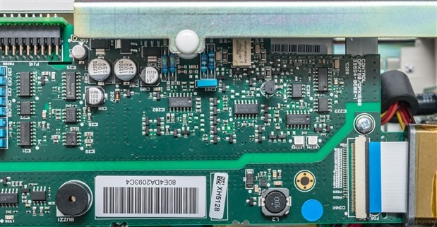
The third image looks towards the front end of the board where, interestingly, some precision through-hole resistors can be seen with the violet 0.1% tolerance band. This area has a few more garden-variety op-amps including LM324M and LM339A. There are two LEDs which shine inside the case – one red and one green, not intended for outside viewing. This board also seems to have some power conversion on this side and interfaces to the front panel via a flexible flat cable with ferrite bead suppression. There is a mechanical element on this board – a Kemet/NEXEM (formerly NEC Japan) UD2-12NUUD2-12NU Low-Signal Relay.
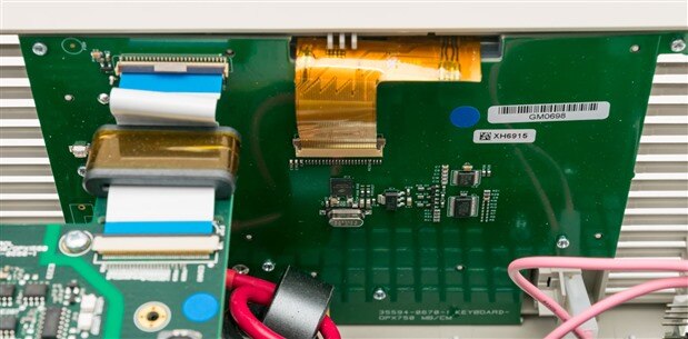

The front panel board doesn’t have much to show from the rear as it’s mostly keys and LCD on the front. It seems there is an Solomon Systech SSD1961G40 Display Controller, an ST LD1117S12TR linear voltage regulator, an NXP PCA9555 I/O port expander and a TI TS2013Q 4-wire dual-touch controller on the rear.
The front output connectors are attached to this PCB as well in the corner, along with the sense leads through connectors. Nearby ceramic and electrolytic bulk capacitors can be seen for local bypassing, with thick cables supplying the current, terminating into rings which are bolted down with spring-washers to ensure good stable contact. The electrolytic capacitors are 105°C rated Rubycon (Japanese brand) capacitors which should be excellent quality.
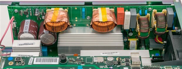
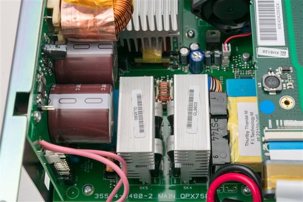
The big and heavy board on the left side of the supply is the PFC board which handles power factor correction and input power duties. On the left of the board are two massive Nippon Chemi-Con KMQ series 105°C rated capacitors. Above that is a Rubycon YXF series capacitor. All of these are of reputable Japanese make, so it seems quality parts have been ordered. The controller seems to be based around an TMS320F28027 C2000 real-time microcontroller. There are some large inductors which are shielded with copper tape.
Closer to the input, this board also has a relay from TE Connectivity next to a 7W 100Ω ceramic resistor, perhaps a soft starter of some sort. Below that is a Jamicon capacitor – the only non-Japanese electrolytic I managed to spot. Near that appears to be transformer or inductor from F.I. Technology Limited which is a local-to-them manufacturer. The part is dated 03/2021 making this unit relatively “fresh” off the line. Right at the bottom of the board is a Matsushita/Panasonic electrolytic capacitor right near the input fuse which is buried right at the bottom edge of the PFC board. The placement of the fuse is a bit of a strange one as it makes fuse replacement a bit tricky without disassembling the whole unit due to the limited clearance and access to the holder. That being said, with such a large value of fuse (15A, time-delay), it shouldn’t blow unless something catastrophic has happened to the unit, so replacement is not usually necessary.
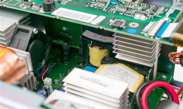
Staring through the gaps into the main board, there are a number of chunky through-hole semiconductors mounted to heatsinks. Other transformers from F.I. Technology can be seen. Some are even tucked underneath the control PCB, making use of all the available space. Another few Rubycon capacitors can be seen.
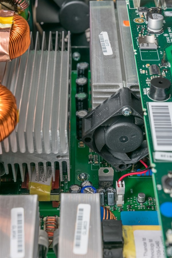
Ah, a venerable LM7812CV has appeared! Unfortunately, that is right next to a small 40mm Sunon fan which is directly attached to a heatsink. Having another fan inside the unit can mean another maintenance item if it should get dusty or the bearings fail. My experience with small fans generally are not that great in terms of reliability. It also seems only secured by a single screw which may ease servicing but also may make it more vulnerable to vibrations in transit affecting its position.
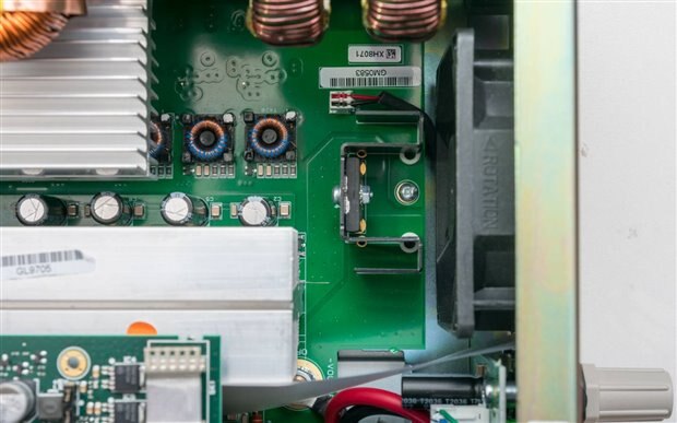
The components seem to leave some free space towards the rear fan, possibly for air-flow reasons. Right in the flow of the fan is this large semiconductor package (perhaps a dual-diode package or a bridge-rectifier package) with its own heatsink, enjoying the “breeze”.
Unfortunately, that is where the peek under the covers end – to get any further down into the unit would require more disassembly which I don’t think is worth the risk at this stage. At least you’ve managed to see inside the unit – it’s a relatively compact configuration made from reputable brand-name parts (especially electrolytic capacitors), includes magnetics from a UK supplier and hides a small fan inside. Aside from the nestled placement of the fuse and the use of the microSDHC card which seems a little suspicious, everything else seems to be of excellent quality.
What Do You Remember?
I was a little suspicious of the microSDHC card, so I decided to take a closer look.
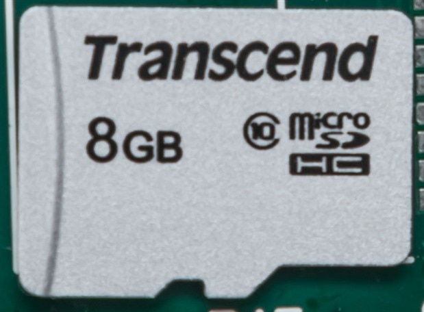
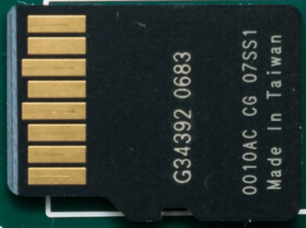
It seems to be a Transcend 300S Class 10 8GB microSDHC card, a consumer-grade device based on TLC flash. While it’s not nasty like the most modern QLC-based devices and the application is likely to be read-mostly, it’s still a little unexpected to see the use of such a card as opposed to a “hardier” industrial card that has been qualified for such applications.
My experience of using consumer-grade cards in read-mostly applications is very mixed – the reliability and performance really depend on the controller. I’ve had cards which after a few years tend to read back slowly or error out the first few times until the data is recovered. Others fail suddenly, but there are many that work just fine but who knows for how long. It would be more common to see the use of SPI/QSPI NOR Flash in such applications or even EEPROMs if the data volume is very small.
Regardless, I decided to investigate carefully by using a write-protected reader to ensure the card would not be damaged, taking an image and then examining that forensically. I determined the card to be mostly empty save for the following directory structure and files which occupied a very small amount of space.
DISCLAIMER: Accessing and modifying the embedded microSDHC card is not an operation supported or recommended by the manufacturer. Do so at your own risk. You may cause the data on the card to become damaged and render your power supply inoperative in the process!
\---_QPX750
+---FIRMWARE
+---HELP
| 1.TXT
| 2.TXT
| 3.TXT
| 4.TXT
| 5.TXT
| 6.TXT
| 7.TXT
| 8.TXT
| TOPICS.TXT
+---PRTSCN
+---SETUP
\---SYSTEM
AIM_TTI.BMP
CALL.SET
CAL_LDEF.CAL
CAL__LAT.CAL
CIMON.SET
SYSTEM.SYS
TESTKB.SET
TOUCH.CAL
VENDOR.SYS
The use of only a small part of a large card is advantageous as it will improve endurance by giving the controller plenty of spare blocks to rotate data in and out of. From what I can tell, the FIRMWARE folder is probably used to hold firmware update downloads to the instrument while the update is processed. The HELP folder actually contains the help data and examining the faulty help files reveals that they are indeed UTF-16 with a byte-order mark, so the “null” byte every second character is what is causing the display anomalies, as suspected. The PRTSCN folder is for a screen capture functionality which doesn’t seem to be available in the production firmware. The SETUP folder is an area where power supply settings can be stored. The SYSTEM folder contains the boot-splash image, calibration defaults and latest files, user settings, touch-screen calibration data and vendor-specific information which may be used to re-badge this unit for other companies. Examining some of these files seems to show that the allocated address from my DHCP server was written into at least one of the files, so the card does see some small writes from time-to-time.
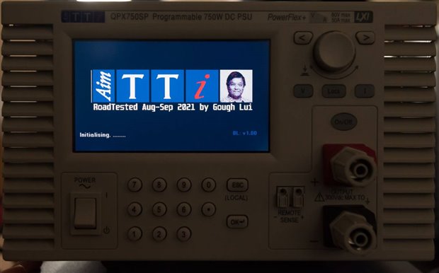
For some fun, I decided to modify the specially-formatted palletised BMP boot splash file to display a picture of me and some text. Now I can truly call this power supply my own!
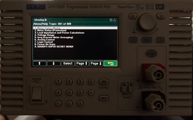
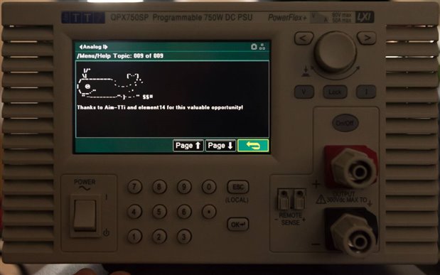
Next, I decided to write in some modifications to the HELP files, and that worked as well as you might expect! It seems the system was designed to be easily extended, but I suspect there will be very few users willing to read the limited text-only help off the small screen of the power supply, so its inclusion is perhaps not all that practical.
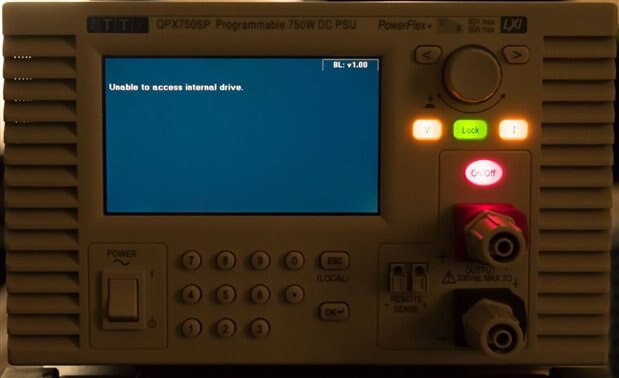
A key question is what happens to the supply if the microSDHC card fails or is damaged. I removed the card and tried to boot the supply and it hangs at the error “Unable to access internal drive.” It seems that the bootloader and firmware may well be programmed onto the SoC, but it requires access to the device to retrieve the system-specific data to actually configure itself. As a result, I think it is wise to ensure you have backups of the data just-in-case that card fails some time down the track.
Conclusion
I couldn’t resist the opportunity to round-off this review by taking a peek under the covers. What I saw was quite impressive – internals that occupied most of the space available inside by having PCBs span across the bottom, sides and even sticking out like a mezzanine. The components were practically all from reputable manufacturers, some a bit old-fashioned, with appropriately high-precision parts where needed. Electrolytic capacitors were well-chosen with practically all units from reputable Japanese brands. Magnetics appear to have come from a local supplier (to them), F.I. Technology. Construction quality is excellent, although the system does have a buried 40mm Sunon fan inside that is secured by only one screw to a heatsink.
The other questionable aspects were the placement of the mains fuse in the bottom corner of the PFC board where it cannot be easily accessed. While a fuse blow would be very unexpected given its large 15A time-delay rating, replacement is complicated by the limited clearance due to neighbouring components.
Another questionable aspect, from my view, was the use of a consumer-grade Transcend 300S 8GB microSDHC card using TLC Flash to hold critical system information that is required for the operation of the supply. Conventionally, perhaps an SPI/QSPI NOR Flash component would be used to store the data, but their choice of microSDHC could also have been satisfied with industrial-grade MLC cards which may have longer lifetime. That being said, with such a small amount of data and a read-mostly operation, provided the controller does a good job of managing read-disturb and slow charge-leakage, the set-up should still work just fine assuming the card stays in place. That being said, I felt more comfortable backing up the card’s data, just in case, even though this is not a manufacturer authorised procedure. That also gave me the opportunity to modify some of the data (at my own risk) and have some fun with it.
---
This chapter is a part of the Aim-TTi QPX750SP 750W PowerFlex Programmable DC Power Supply RoadTest Review. More detailed chapters are linked from within the main review.

