


This chapter is concerned with instrument performance, perhaps one of the most important metrics of test and measurement equipment. It involves in-depth testing of power consumption, charging current profile, analog channel accuracy, digital timing channel accuracy, digital logic channel thresholds and alarm output latency. This section is very time-intensive, especially when analysis is concerned.
Power Consumption & Charging Profile
The DAS240-BAT is powered from a 15V 4.5A power supply, although the unit itself is marked as having an input of 15V 1A. It also has an internal battery which can be used to run the unit away from mains supply. In order to determine power consumption and charging profile, power was supplied from the Rohde & Schwarz NGM202 Power Supply through a home-brew banana to barrel plug cable so that the consumption of the DAS240-BAT can be measured continuously as the unit is running, charging or both. The battery was emptied by running the unit until it shuts down automatically prior to all testing.
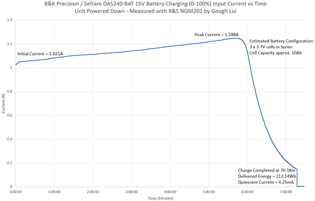
With the unit powered down and plugged into the power supply on an empty battery, the battery takes 7 hours and 18 minutes to charge, delivering a total of 112.14Wh. I estimated the cell capacity to be approximately 10Ah based on these figures alone. Charging started with an initial current of 1.021A, peaking up to 1.248A.
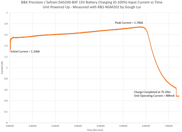
With the unit powered up, the charge time was recorded as virtually identical at 7 hours and 20 minutes. The initial current was 1.336A with a peak current of 1.746A and an operating current of 484mA. This suggests the consumption of the unit is around 7.26W when operating with a fully charged battery, peaking at 26.19W while charging. A higher consumption may occur when additional modules and USB devices are connected – it seems that 2A or 2.5A is all that is necessary, so the power supply provided has plenty of margin which should mean it operates cooler and has a longer lifetime.
For battery-life related information, please see Ch6 – Simulated Field Tests. For battery-pack related information, please see Ch7 – Teardown.
Analog Channels
The analog channels form the bulk of the acquisition capability on the DAS240-BAT and thus, I spent quite a bit of effort trying to characterise the performance of these channels.
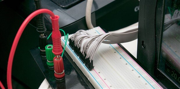
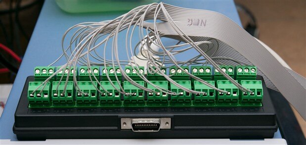
In order to do this, I used 28AWG ribbon cable with one conductor per connection, resulting in a total of forty wires – twenty positive and twenty negatives. Wire ends are screwed into the terminal blocks, while the other end is soldered to header pins in groups of four and heat-shrinked. A breadboard power bus is used to distribute the test signals to all channels equally.
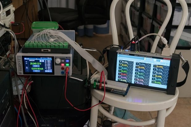
The test signals were generated from a Rohde & Schwarz NGM202 power supply – the most accurate unit in my current portfolio of test equipment. By automation using pyvisa and my pymodbus-based client, I am able to set the voltage on the supply and read the results from the DAS240-BAT remotely and automatically.
Accuracy
To determine accuracy, testing was performed with voltages generated at 1mV intervals by the NGM202 with the readback value being taken as the “true” voltage with its noted tolerances. The DAS240-BAT results were read across all 20 channels, repeated 32 times for a total of 640 readings at each voltage point. The average, maximum and minimum error values were computed across all 640 readings and thus represent an aggregate across all channels. Please note that due to timing issues, the first readings from the first channel sometimes reflected the voltage from the previous step, resulting in minimum errors which are 1mV below the actual performance and are to be disregarded! As the mean is computed over so many values, the stray outlier values do not have a significant impact on the measured average error. The experiments were repeated across the 50mV, 100mV, 500mV, 1V, 2.5V, 5V, 10V and 25V ranges only, due to the limitations of the NGM202’s output capability in terms of its resolution and output range. Prior to each test, an automatic calibration was conducted on the DAS240-BAT after observing a minimum 30-minute warm-up to ensure that readings should meet specifications.
50mV Range
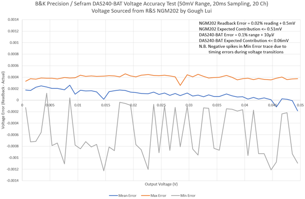
The first test was at 50mV where the expected error is below 0.06mV. As mentioned above, there will be spikiness in the minimum error due to timing errors – the higher reading is the correct one. Unfortunately, this test is rather inconclusive as the NGM202 is expected to contribute up to 0.51mV of error thus we cannot be sure where the source of the reading error is. The mean reading error is in a range of about -0.2mV to +0.3mV.
100mV Range
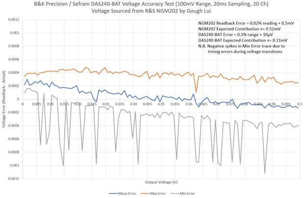
The test at 100mV has an expected error of below 0.11mV, although the NGM202 would be expected to contribute up to 0.52mV of error. The test is not very conclusive, for similar reasons. The mean error is between -0.2mV to +0.3mV.
500mV Range
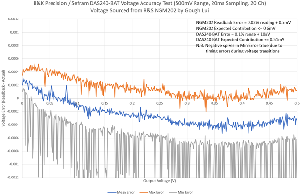
By 500mV, the expected error of under 0.51mV is comparable to the contribution from the NGM202 of 0.6mV. The mean error ranges from -0.5mV up to +0.3mV, which now falls inside the expected margin of error even though the error contribution is likely to be spread across both units. Based on the maximum and minimum error, individual readings may be up to 0.4mV in error compared to the mean.
1V Range
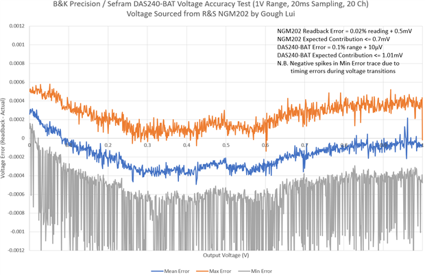
As the voltage increases, the error contribution of the NGM202 reduces. The DAS240-BAT is expected to contribute up to 1.01mV of error with the NGM202 contributing up to 0.7mV. In this case, the whole range (individual and mean readings) fit within the expected error range which confirms the unit meets and likely beats the accuracy specifications as the mean error is still very similar to previous ranges.
2.5V Range
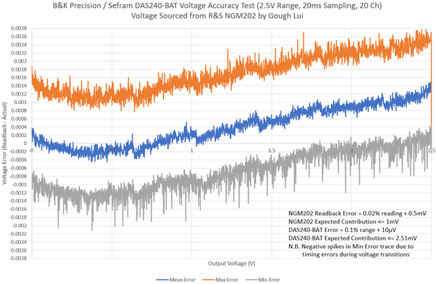
Expanding up to 2.5V, the DAS240-BAT is expected to have up to 2.51mV of reading error with the NGM202 contributing up to 1mV. This time, the max error peaks just exceed the DAS240-BAT specification ever so slightly when ignoring the NGM202’s contribution. The mean error seems to have an upward trend towards the higher end of the range, reaching close to 1.3mV. It is concluded that the DAS240-BAT is likely to have met and beat the accuracy specifications.
5V Range
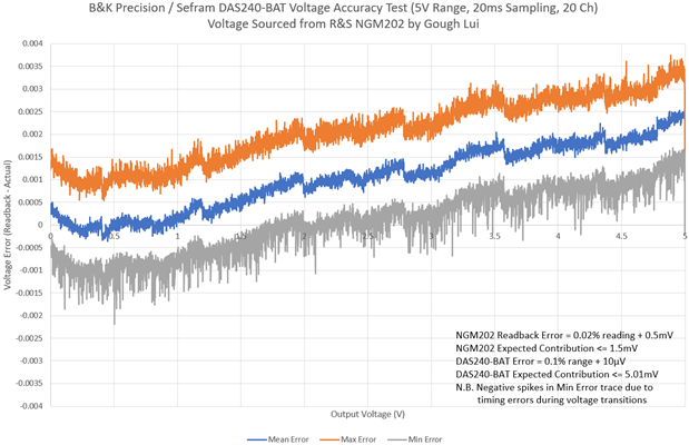
This trend continues up to the 5V range with an expected error up to 5.01mV with a 1.5mV contribution from the NGM202. In this test, all of the readings fall within the expected DAS240-BAT error range, but there is a continuing upward trend in errors. Towards the end, the offset of the reading causes the upper values to be read as the maximum value as the unit does not correctly report over-range over Modbus TCP, hence causing the “drop” in error at full scale.
10V Range
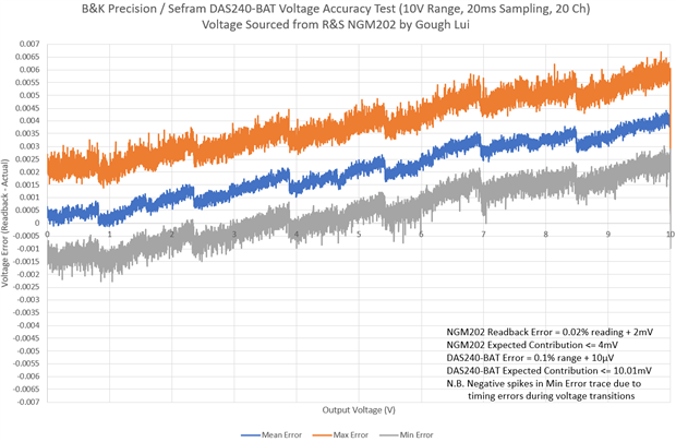
The 10V range is a carbon copy of the 5V range, with the resulting error readings fall completely within the DAS240-BAT error range, indicating the instrument beats the accuracy specifications.
25V Range
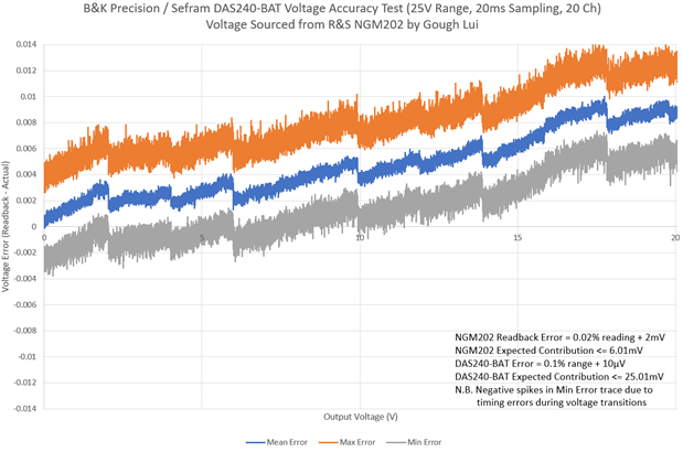
The 25V range could not be completely tested as the NGM202 tops out at 20.060V. The same trend continues with all measurements within the expected error range for the DAS240-BAT. Thus, we can conclude that it is likely that the DAS240-BAT meets and beats the specified accuracy for the analog input channels.
Warm-Up Profile
To assess the drift in analog channel performance with regards to instrument warm-up, the instrument was pre-configured for a single channel active on the ±10V range at the shortest sampling interval (1ms) and shut down for six hours. During this time, a fixed 5V output from the Rohde & Schwarz NGM202 was generated throughout all six hours with the room temperature remaining stable at 23°C and within specifications. The DAS240-BAT was then powered up and acquisition was performed for 30 minutes.
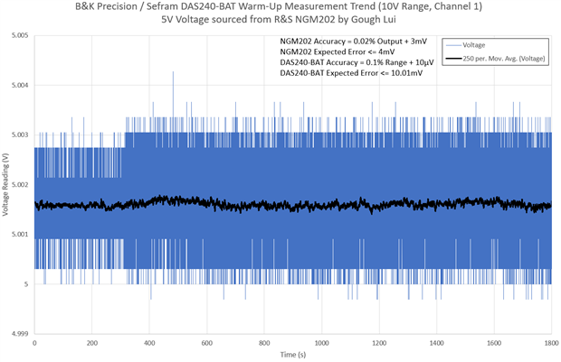
The graph seems to illustrate there is not much of a warm-up trend at all, with readings seemingly stable from cold. There is a certain amount of reading noise, so a moving average of 250 samples (0.25s) was taken to try and detect any underlying trends, but whatever is present appears just to be a random walk noise. This illustrates that warm-up impacts appear to be negligible when the instrument is used at room temperature.
Digital Timing Channels
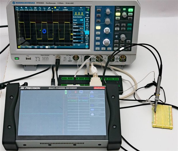
The DAS240-BAT has four digital timing channels, labelled K1 to K4, tolerant of voltages up to 24V. Timing functions include frequency (or RPM), PWM and counter functions. Testing of the first two were undertaken by using the Rohde & Schwarz RTM3004’s onboard function generator to provide test signals under SCPI remote control with results collected via Modbus TCP. Testing is performed on a range of signal frequencies with a 0-5V logic level. The counter function appeared to operate satisfactorily, although the minimum pulse width was not specified and in some borderline cases, it is possible to have the occasional erroneous value, but on the whole it usually operated flawlessly. The other functions, however, deserve much closer inspection due to the complex number of variables at play.
Frequency
Surprisingly, the DAS240-BAT allows for setting the frequency measurement range far wider than the claimed 10kHz in the datasheet, allowing up to 200kHz. I suspect this is not warranted, although it was also worth testing.
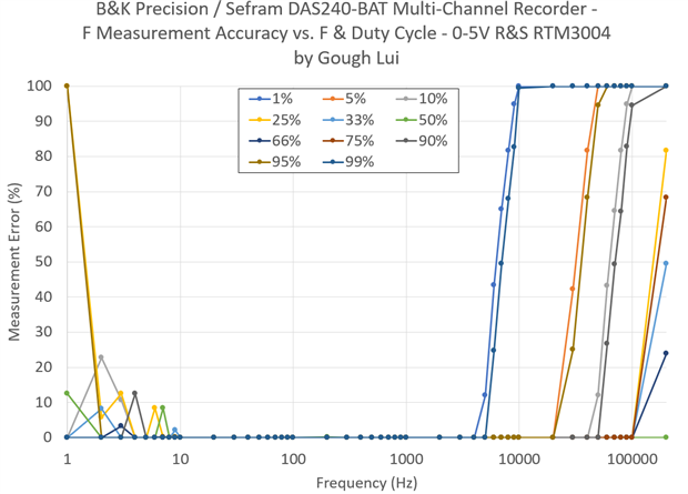
It seems that measurements above 4kHz are not reliable, but the error is dependent on the duty cycle of your input signal, with the inverse duty showing similar characteristics (i.e. 1% vs 99%, 5% vs 95%, etc). Measurements at the low-end are also unstable.
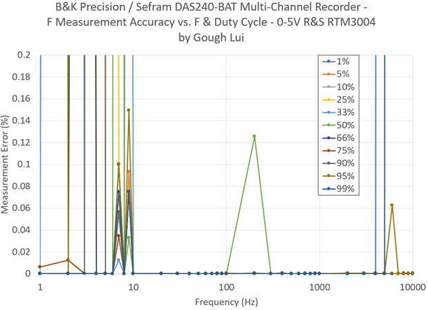
Zooming into the specified range of the DAS240-BAT, it can be seen that the frequency measurement is not without issues. The area from 1 to 10Hz seems to result in rather unstable values that exceed the stated 0.1% error, whereas at 200Hz/50% duty cycle there is an outlier. At 4kHz and above, there seems to be challenges with properly measuring 1%/99% duty cycle signals.
Duty Cycle
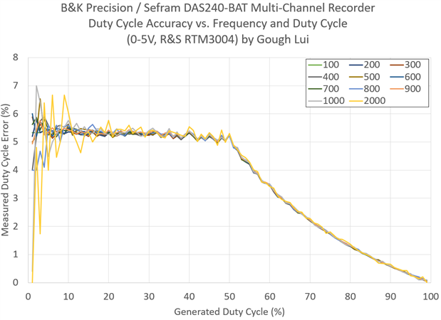
The duty cycle was measured at 100 to 2000Hz at each 1% step from 1 to 99%. The measurement errors were much greater than the 0.1% specification, reaching about 5-6% for readings below 50% and decreasing as a curve towards 100%. This suggests to me that there may be something wrong with the internal calculation of duty cycle, as the error is mostly independent of frequency especially above 20% duty cycle. Low duty cycles and high frequencies also seem to pose challenges for the DAS240-BAT. This has been reported to B&K Precision for improvement.
One possibility is that the RTM3004 could have contributed to error, so I tested the generated output from the function generator on one of the analog channels of the RTM3004 and the measured duty cycle matched the setting within 0.1%, indicating the error was with the DAS240-BAT and not the RTM3004.
Digital Logic Channels
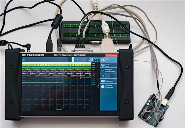
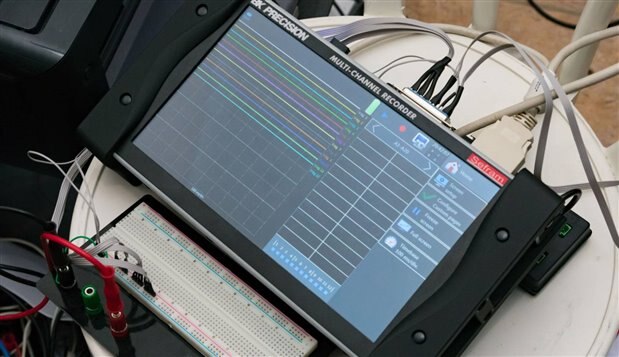
The DAS240-BAT has twelve digital logic channels which are tolerant of voltages up to 24V. Testing the logic channels required the construction of a wiring harness to access all the channels.
Counter Test
A simple test of all the logic channels can be achieved by inputting a digital counter that iterates over all possible 12-bit values at the maximum supported 1kHz rate. I achieved this using an Arduino Uno with the DirectIO Library. The code is as follows:
// Fast 12-bit counter using DirectIO
// by Gough Lui - January 2020

#define ARDUINO_AVR_UNO 1
#include <DirectIO.h>

OutputPort<PORT_D, 2, 6> highport;
OutputPort<PORT_C, 0, 6> lowport;

unsigned int count;
unsigned long ltime;

void setup() {
  highport.setup();
  lowport.setup();
  count = 0;
  ltime = 0;
}

void loop() {
  if(ltime != millis()) {
    ltime=millis(); // Output at 1kHz rate
    highport = (count>>6) & 0x0000003F;
    lowport = count & 0x0000003F;
    count = count + 1;
  }
}
Once loaded onto the Arduino, I used a USB port on the DAS240-BAT to power the Arduino.
The signal was correctly shown on the display and resolution of the counter even at the lowest bit was acceptable with only a slight occasional jitter visible on the trace when zoomed into the maximum level. The interface is not optimised for searching through for events on a given logical combination, however.
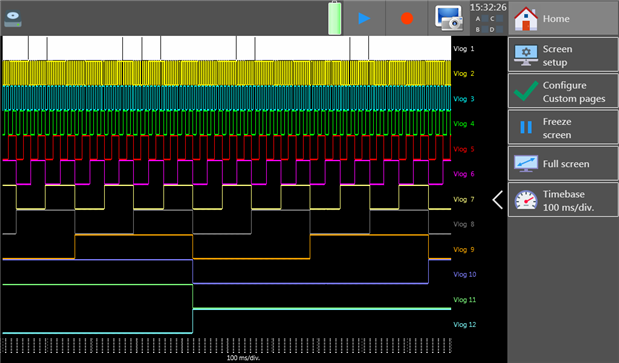
Alarm conditions using all digital inputs were also tested. The expected period of alarm is 4096ms based on singling out one unique 12-bit value, however, the recorded time is longer. It seems that alarms are sometimes missed, perhaps as the system cannot handle such rapid input changes.
Digital Signal Threshold
The digital signal threshold is the point where the channel “decides” between a logic zero and a logic one and determines the compatibility of the input with various signalling schemes.
In order to test this, all logic channels were fed by the Rohde & Schwarz NGM202 power supply and swept at 1mV intervals both upwards from 0V to 5V and downwards from 5V to 0V. Values were recorded remotely, as similar with the prior experiments.
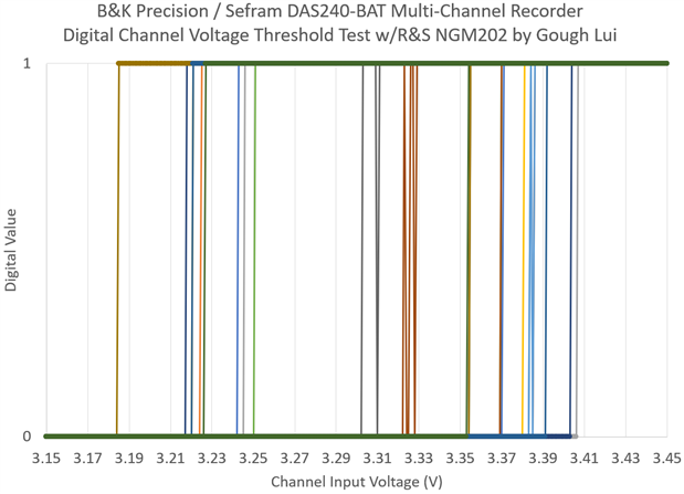
Each channel appears to have a slightly different threshold, but it averages around 3.3V. Reliable zeroes are achieved below about 3.18V and reliable ones are above 3.41V. This makes it compatible with 5V TTL and high-level (up to 24V) signalling, but 3.3V TTL is insufficient to reliably drive the inputs.
Alarm Outputs
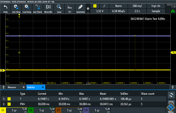
The DAS240-BAT is capable of generating up to four independent alarm channel outputs at 5V TTL levels subject to various combinations of analog threshold or digital logic states. Testing of these outputs was achieved by using the Rohde & Schwarz RTM3004’s inbuilt signal generator to produce input signals which could be used to trigger the outputs.
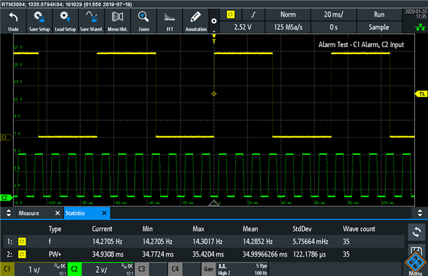
With a 100Hz signal input and a condition which should result in the alarm output following the input, it seems that the alarms are only updated at a rate of about 14Hz with a pulse width of about 35ms. This makes it less suitable for applications generating a high-frequency of alarms.
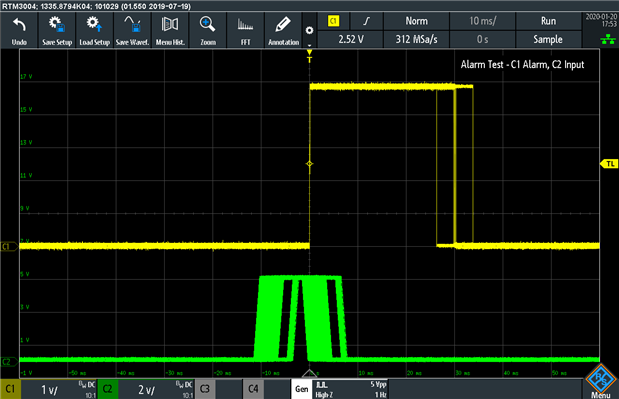
The propagation delay of the alarm signal is variable between around 4 to 10ms, which is probably fast enough for most expected applications, except for the most demanding requirements.
Conclusion
Verification of the DAS240-BAT’s performance was done with the help of a Rohde & Schwarz RTM3004 Oscilloscope, NGM202 Power Supply and Arduino Uno board, with copious use of Python-based automation techniques.
The power requirements of the DAS240-BAT were determined to range from a peak of 1.248A when charging when powered off, to a peak current of 1.746A when charging and powered on. It seems likely that true peak requirement is closer to 2A or 2.5A which is more than the 1A printed on the rear of the case, but less than the 4.5A power adapter it is supplied with. As a result, it seems likely that the supplied power supply would have a long reliable service life due to this. Battery recharging time from empty appears unaffected by unit operation, coming in at around 7 hours 20 minutes regardless with a total delivered energy of 112Wh.
Analog channel accuracy appears to be well within the specifications, although at the lower ranges, it was difficult to draw firm conclusions due to the large error contribution from the NGM202 compared to the DAS240-BAT’s specification. Unfortunately, as I do not possess any better test equipment, further tests of the lower ranges of 1V and below is difficult. Above this, it seems clear that the unit is able to meet and beat the claimed accuracy levels with the resulting error remaining within the boundaries even when discounting the NGM202’s contribution. The unit also appeared to be quite stable from cold, not exhibiting any clear warm-up trend at the standard room temperature.
Digital timing channels were tested with 5V-level signals, with the counter found to be operating correctly provided the pulse widths were sufficiently wide, having the occasional erroneous value in case of high frequency/short duty cycle pulses. The frequency measurement range appears possible to set values outside of the datasheet specifications up to 200kHz however, readings were suspect especially below 10Hz and above 4kHz depending on the duty cycle of the signal with inverse-duty showing similar characteristics (i.e. 1% vs 99%, 5% vs 95%, etc). One outlier was also recorded with regards to frequency. Duty cycle measurements, however, were found to be unreliable and in significantly higher error (up to 6%) compared to datasheet specification, being particularly poor for signals below 50% duty. This seemed to be frequency independent, suggesting a potential software issue with the way the DAS240-BAT calculates duty cycles and has been reported to B&K Precision for future improvement.
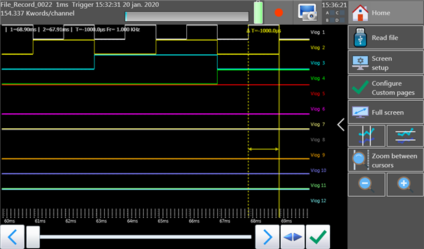
The digital logic channels were tested by iterating all possible 12-bit values using the Arduino, showing the signal could be resolved even at the maximum 1kHz sampling frequency. Testing of the alarm output was also undertaken, with some alarm events based on this signal input being delayed or missed entirely as it seems the DAS240-BAT could not keep up with the input. Digital signal level thresholds were measured to be about 3.3V, with reliable zeroes below 3.18V and reliable ones above 3.41V making digital inputs suitable for use with 5V TTL and high-level signals, although incompatible with 3.3V TTL.
Closer testing of the alarm outputs was able to show that alarm outputs could only be generated at a rate about 14Hz, with a propagation delay variable from 4 to 10ms which would be fast enough for many applications except perhaps the most demanding research and development needs.
---
This post is part of the B&K Precision/Sefram DAS240-BAT Multi-Channel Recorder RoadTest Review.
Top Comments
-

three-phase
-
Cancel
-
Vote Up
+1
Vote Down
-
-
Sign in to reply
-
More
-
Cancel
Comment-

three-phase
-
Cancel
-
Vote Up
+1
Vote Down
-
-
Sign in to reply
-
More
-
Cancel
Children