


Since some RoadTest review readers get bored of looking through unboxing, the unboxing process has been moved into this separate blog post.
Unboxing
For this Infineon Gate Driver with Truly Differential Input RoadTest, a special package from element14 arrived, safely packed with crumpled paper to prevent damage.

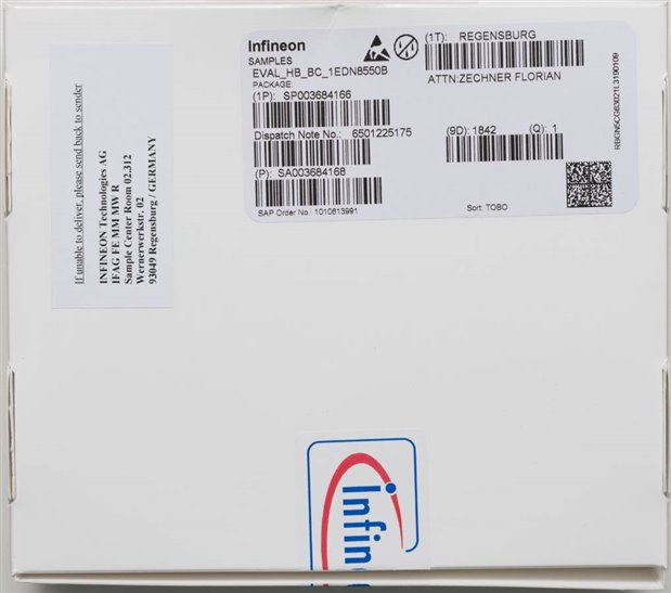
The MOSFET Gate Driver IC Evaluation Board comes packaged in a thin colour cardboard box. The rear is host to a number of labels indicating the order process which it has gone through to get to me.
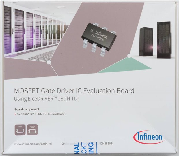
The box itself is ordinarily sealed, however, in my case, the seal had been broken. Along the sides of the box are contact numbers for Infineon’s support services, available in many countries around the world. It seems they like the number ‘951’ – perhaps this sounds like Infineon in some language? The other side of the board is adorned with a web address and QR code for accessing the documentation.


Inside the box, it seems to be rather loosely packed in anti-static wrapping, although everything seems to be serial-numbered including the one sheet of documentation.

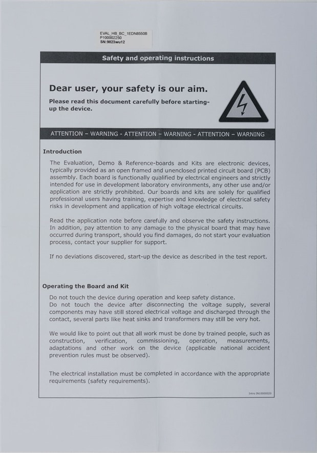
The only documentation inclusion is the one sheet of disclaimers which seem to make it sound more dangerous than it actually is.
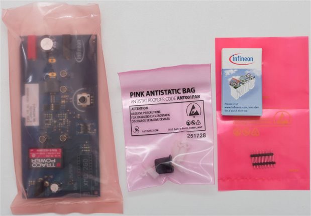
The remainder of the box are the useful bits, which includes the main evaluation board, a bag with a knob and four nylon standoffs with associated nut, another bag with two header-pin rows and an XMC2GO in its box, which is used to generate the gate drive signals.
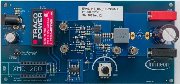
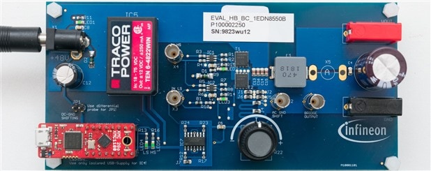
The evaluation board is built on a double-sided blue-coloured PCB. Power input is provided through a 2.1mm centre barrel jack on the left side, which is converted by a Traco Power TEN 6-4822WIN to 12V for the MOSFET drivers. The board features integrated DC ground shift adjustment via potentiometer and AC ground shift adjustment through removal of SMD shorting resistors J1-J6. Bridge output is via 4mm banana sockets on the right side of the board, while the gate drive signals are generated by an XMC2GO which plugs into the header rows in the bottom-left of the board. Signals can be examined through the oscilloscope probe sockets pre-mounted on the board, which appear to best suit Teledyne LeCroy probes.
Like IKEA furniture, the board does need some assembly to complete. In our case, X5 is a space for a current-clamp loop and wire needs to be jumpered across the pins to monitor the inductor current. Likewise, the knob needs to be attached to the potentiometer and the standoffs need to be assembled to elevate the board off the bench for cooling and to avoid inadvertent short circuits.
The board underside has a few capacitors and resistors, with a space for mounting your own comparison low-side driver if you wish. The board appears to have some streaks on its finish from the board cleaning process. There is a serial number label and an NFC sticker (seemingly unprogrammed) on the unit as well.
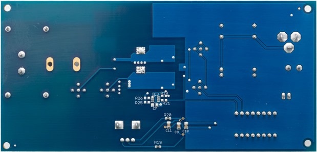
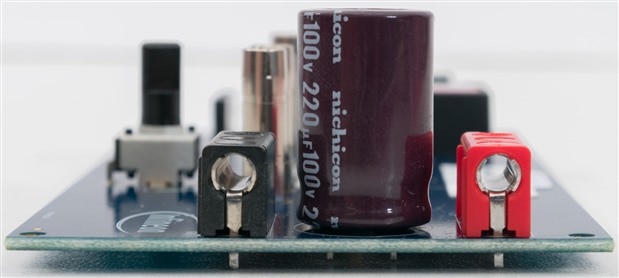
While the board is not intended to be used as a component, it’s interesting to see that quality components have been used, including Nichicon capacitors.

The XMC2GO Board also comes in its own box which is smaller than a matchstick box, it’s pretty cute.

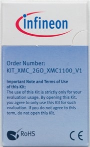
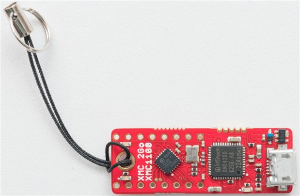
The board itself comes with a lanyard and uses a microUSB-B connector for interfacing with a computer. The unit features the XMC1100 as the main processor and XMC4200 for debugging, with three LEDs and rows of holes for header pins which you will have to solder by yourself. You’ll need to find your own USB cable, but that’s not too difficult.

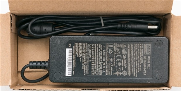
To help us along, element14 have also ordered and included a Meanwell Power Supply, itself worth AU$32.21. This isn’t part of the normal evaluation board order, as far as I know, so those ordering just the evaluation board may have to find their own source of 48V.


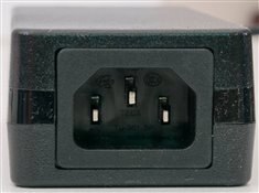
The power supply outputs 48V at 1.25A for a total of 60W maximum, matching the board’s tested rating. It requires a standard IEC cable, not included. Meanwell units are very reputable, so that was nice to see it thrown into the RoadTest.

This is what it looks like with the XMC2GO soldered and plugged in – the header row is fairly stiff and makes good contact.
Conclusion
The EVAL_HB_BC_1EDN8550B board demonstrates the Infineon EiceDRIVER 1EDN8550B, but also gives an opportunity to showcase Infineon’s Optimos BSC026N08NS5 and XMC2GO products. It comes packed in a thin-colour-cardboard box with appropriate anti-static bag protection, complete with even a knob for the potentiometer and nylon stand-offs for the main PCB. The board is double-sided, blue in colour and comes populated with quality components. Documentation is online, with only a disclaimer shipping with the unit. Evaluation requires some assembly, including soldering header-pins, jumper wires and fitment of hardware. It also requires users supply their own microUSB cable and appropriate probes to match the sockets on the board which appear to be designed for Teledyne LeCroy probes. Use of a current clamp probe and differential probes are also recommended due to the various ground levels on the board.
In the case of this RoadTest, element14 have generously supplied a Meanwell 48V/1.25A 60W power supply. Those ordering the board on its own would need to supply their own 48V power supply through a 2.1mm centre pin barrel jack.
The board itself can be purchased for AU$181.28 from element14 AU which appears to be a bit on the expensive side, especially as it is mainly used to illustrate concepts which are illustrated in the freely downloadable documentation. It is, perhaps, most useful for those who might want to better familiarise themselves with the driver and its abilities based on this example design (especially if you don’t believe Infineon), but as the driver itself can be had for around 1% of the price, perhaps others may be better served by purchasing the driver and integrating it into their own test set-up or designs instead.
---
This is a part of the Infineon MOSFET Gate Driver IC Evaluation Board RoadTest featuring the EiceDRIVER 1EDN TDI (1EDN8550B)