


Included in this blog post are some of the juicier details which wasn’t included in the main RoadTest review so as not to “clog” up the review.
Unboxing Extras
What follows are some additional images including close-ups that I didn’t feel needed to be included in the main review, but seeing as I’ve taken and processed the photos, should probably be uploaded somewhere.

The first thing we are greeted with when opening the box is instructions to the RoadTest candidate written by Ed Ku.


The contactor supplied is a DILM7-10 rated at 3kW/400V with a 24VDC coil manufactured 38th Week of 2012. The box is covered with the Eaton logo in blue, and a warning that only “skilled persons may install and commission the devices.” I guess I fit into that category now … *opens the box*.

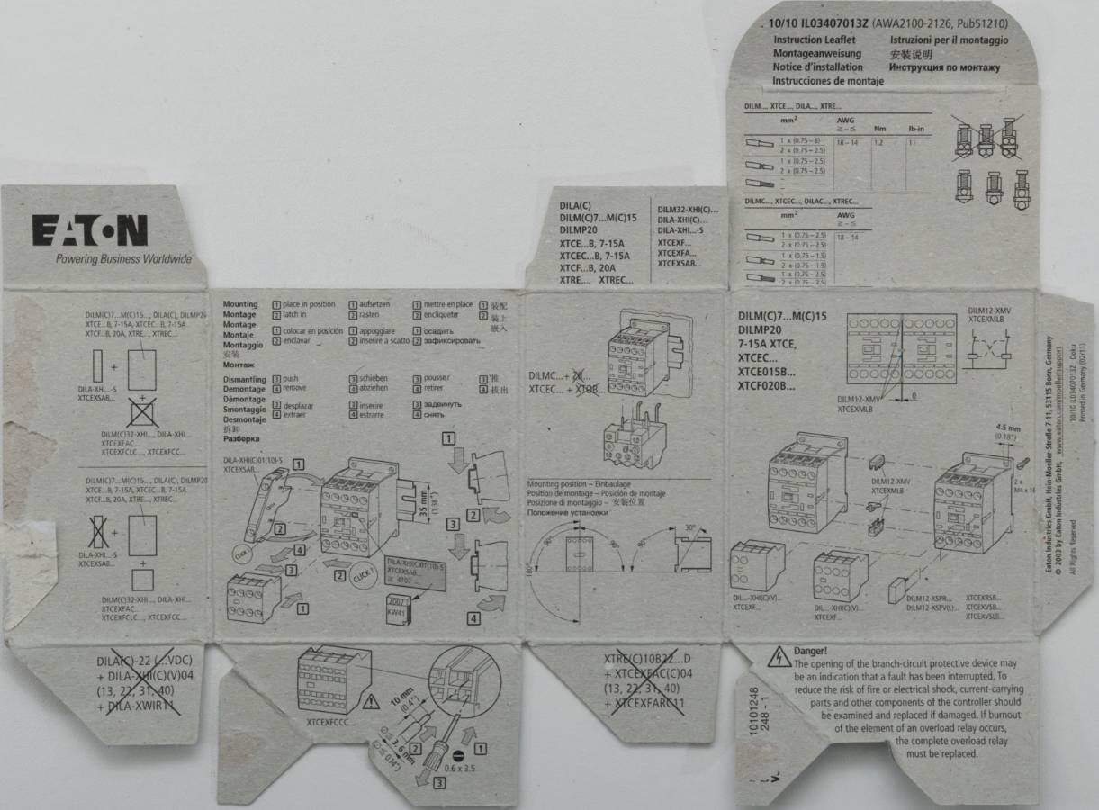
The box internals are also printed and form the manual for the contactor, although the text is a little difficult to understand due to the lack of words in general.
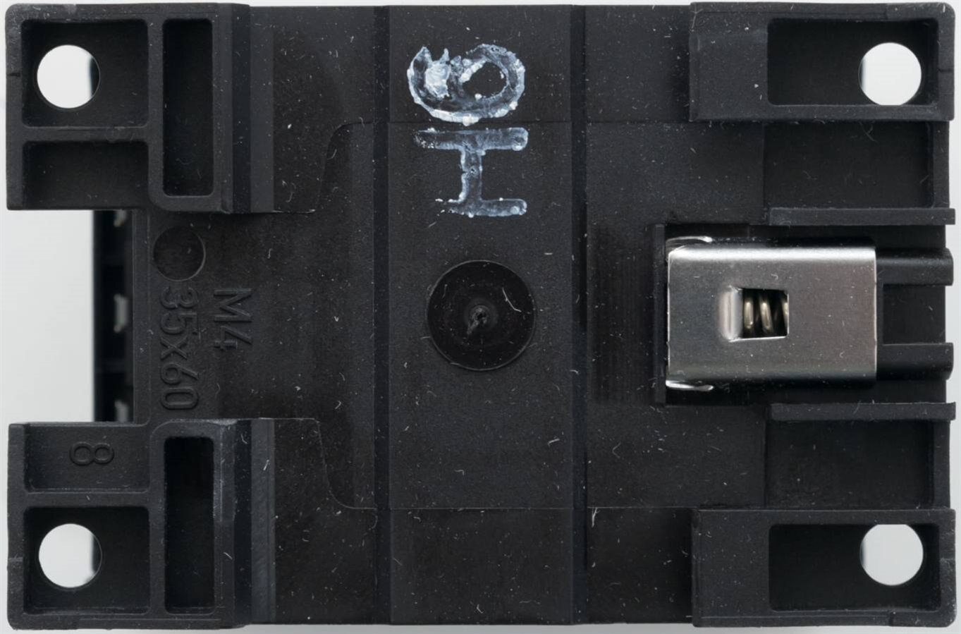
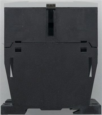
The contactor is DIN rail mounted with a spring loading clip and has a roughly boxy side profile.

Wires enter and exit from the top and bottom faces of the contactor.
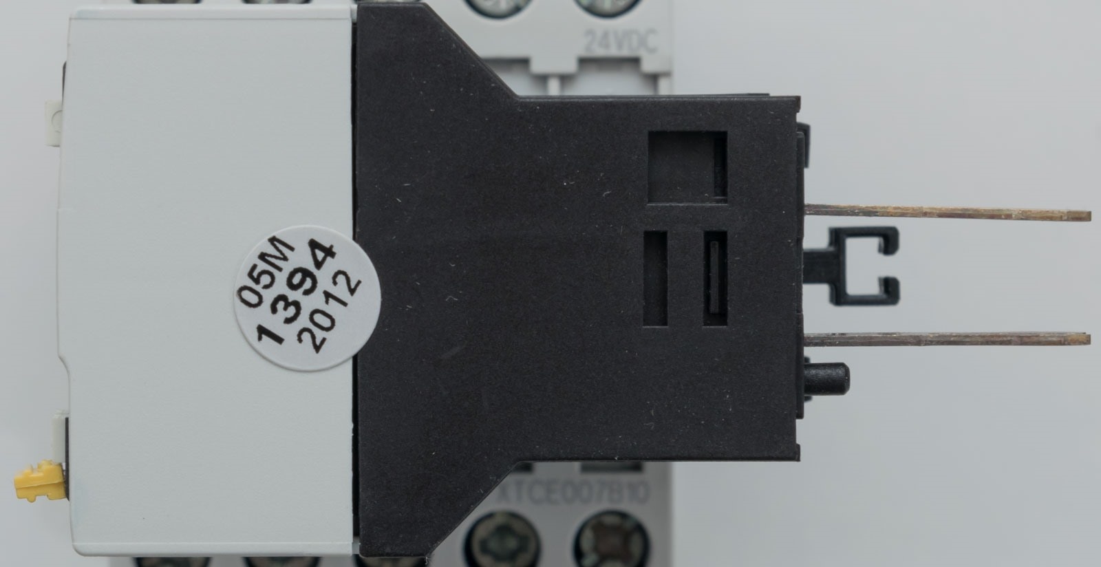
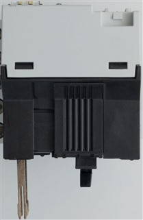
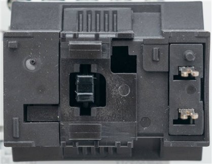
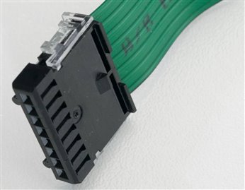
In order to transform the DILM7-10 into a SmartWire-DT device, a DIL-SWD-32-002DIL-SWD-32-002 is used. This has two “forked” contacts which go into slots on the contactor to directly actuate the coil and is held in place by the plastic latching mechanism.
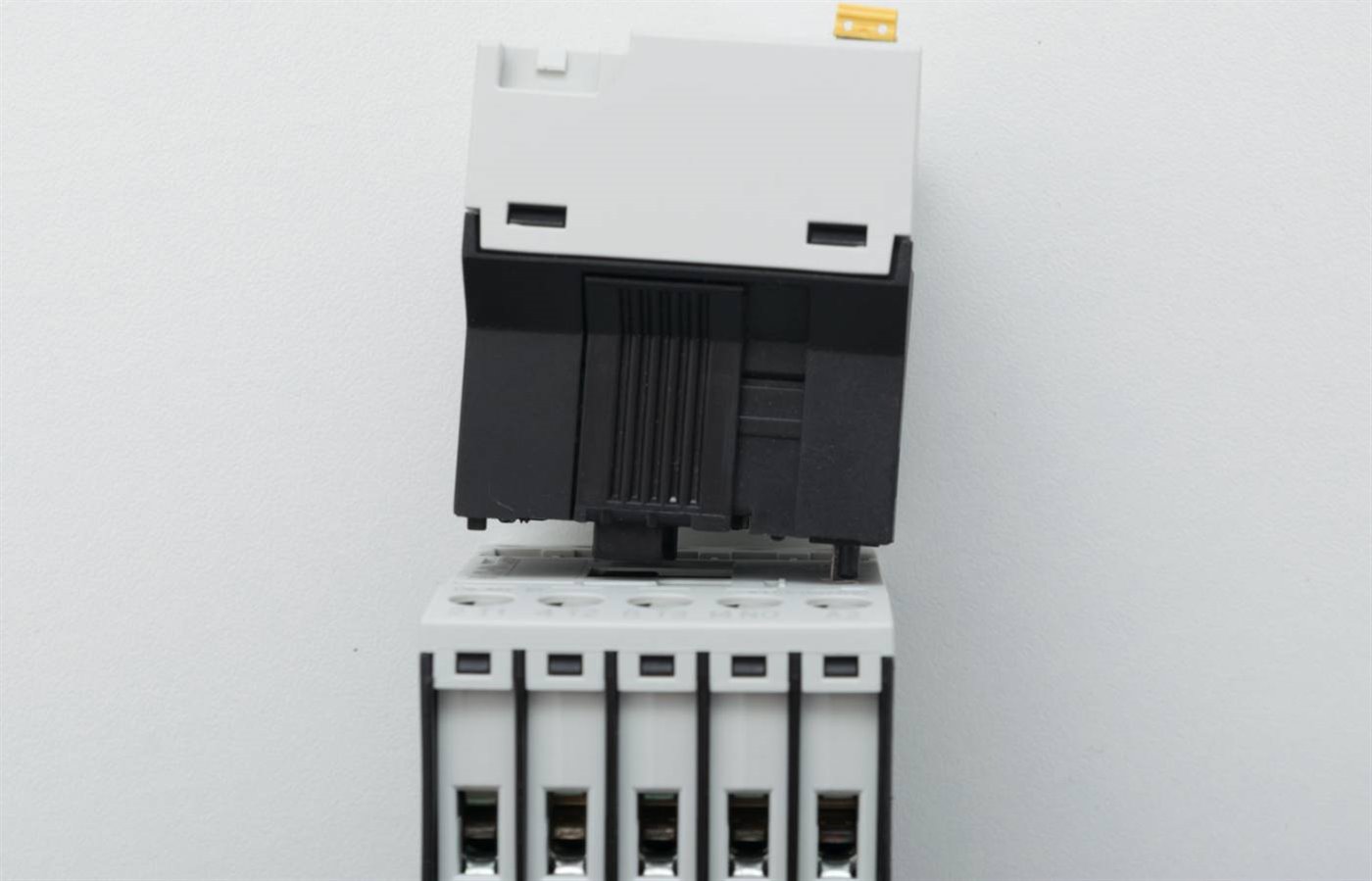
We can see that the mating of the two results in a fairly “tall” profile device which does lever some distance away from the DIN rail.
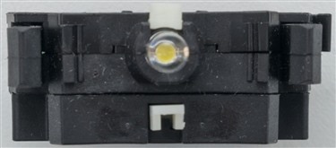
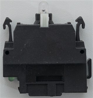

The M22-SWD-K22-LED-W switch modules from all sides.

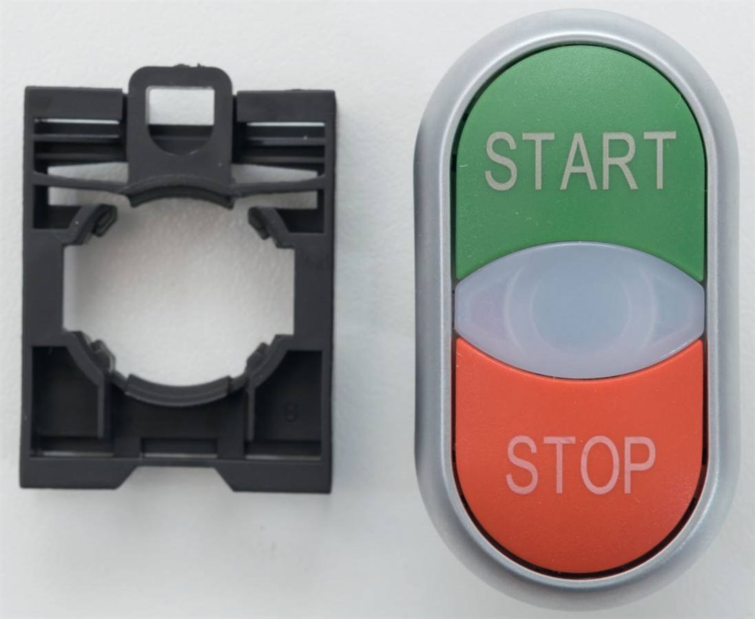
The Pilot button module package.
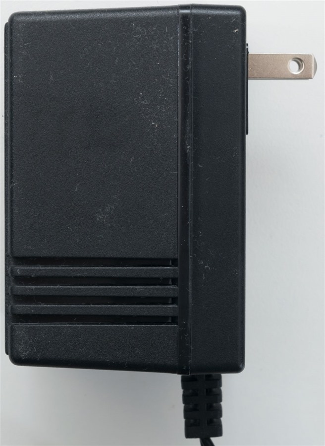
The supplied chunky US transformer which isn’t suitable for my use (unfortunately). Luckily, I have plenty of lab power supplies to use.
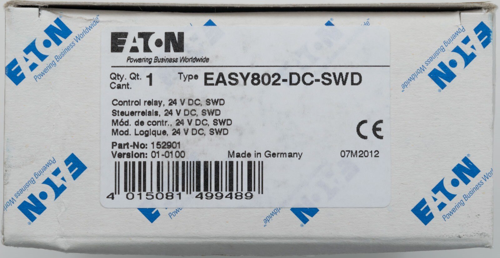
The EASY-802-DC-SWD comes in a very similar box, with a manufacturing date of July 2012.
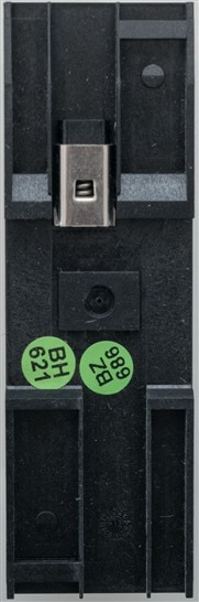
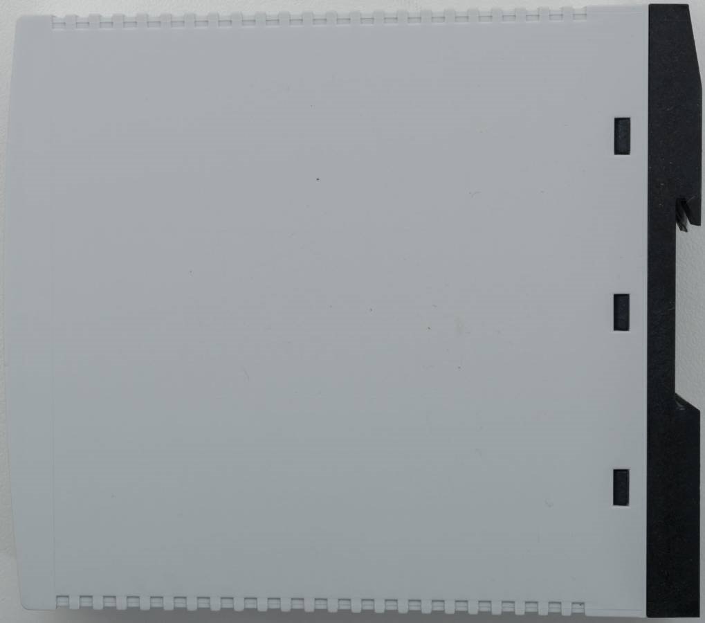
The unit is also DIN rail mounted, as expected, with a screwless design that has a plain cover on one side.
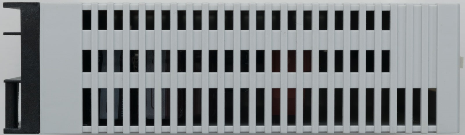
Top and bottom are vented with the SWD Out on the top and no interface on the bottom.
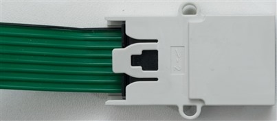
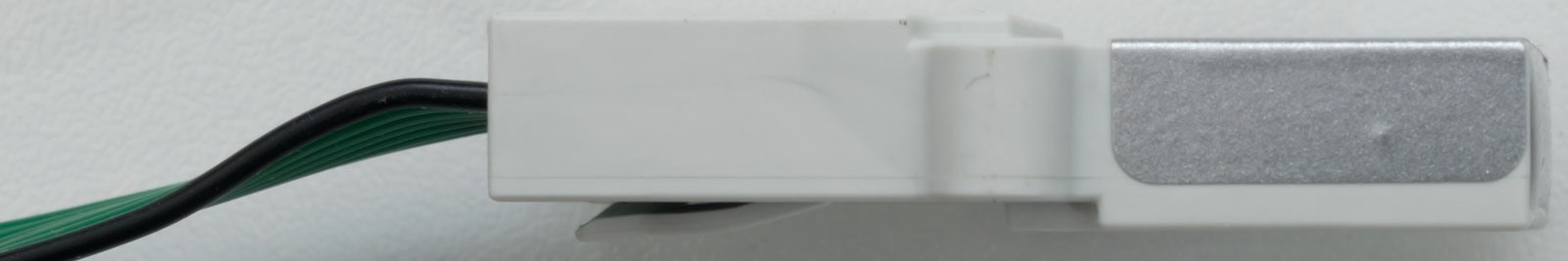
The cable ends are dressed in flat plugs which are IDC crimped. These plugs feature eight connections and the opposing end of the bus is connected to a terminator which absorbs signal reflections, allowing the bus to operate correctly.
Partial Teardowns
For those who want to take a look at the insides, I did take apart the EASY802-DC-SWDEASY802-DC-SWD unit.
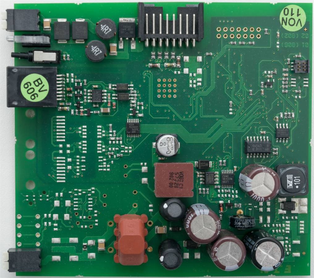
It seems that the PCB is rather sparse and is common to the 802/806 units. The difference is that the 806 has a SWD output as well as EasyNET capabilities and integrated digital I/O. From the top, the PCB has a rather clean look with a bunch of power-conditioning parts including capacitors and inductors and a supercapacitor for date/time backup. The programming interface can be seen from the top and it seems great care has been taken to ensure the interface is electrically isolated for safety – vitally important for the safety of the attached computer and human!
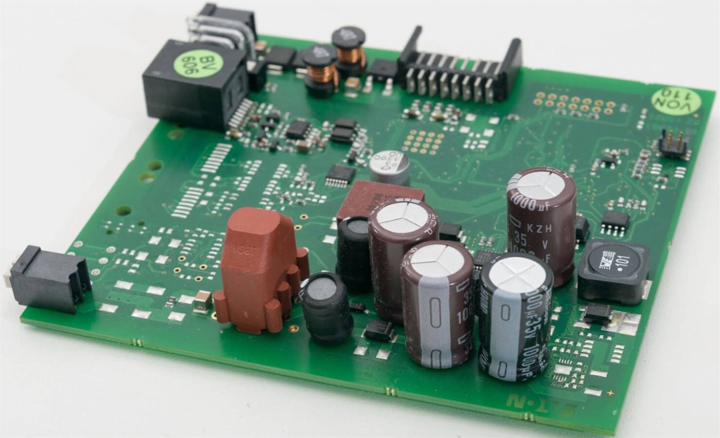

It’s a good relief to see that the capacitors are quality electrolytics from Nichicon and United Chemi-Con. The Eaton logo can be seen in the lower right corner.

From the underside, we see only a few ICs including what appears to be a custom ASIC marked SWD-80P-RS485 003-0809 with the address Swire-D.com. There is a main CPU with a 4Mhz crystal, covered by a label with indicating the V1.00 firmware revision.
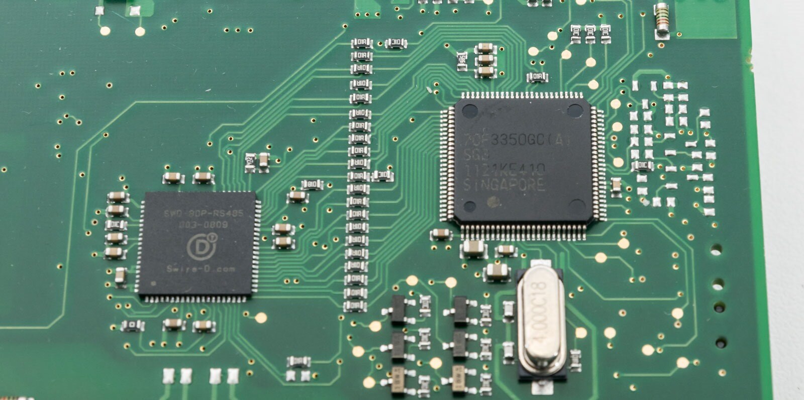
The CPU is marked 70F3350GC(A) and appears to be an NEC V850ES/SG3 32-bit Microcontroller. According to the datasheet, it contains 512kB of Flash ROM, 40kB RAM, 32MHz maximum frequency, 1-ch CAN capability with on-board I2C, IEBus, 8 external + 51 internal maskable interrupts and 2 non-maskable interrupts.
The next thing I tore down was the EU4A-RJ45-USB-CAB1 (01) programming adapter.

The adapter is based around a Silicon Labs CP2102 USB to Serial adapter, but protected by some isolation involving an ADuM5241 Dual-Channel Isolators with isoPower Integrated DC-to-DC Converter and ADM101E Craft Port Tiny RS-232RS-232 Transciever. Three wires go to the RJ45 plug. The PCB appears to also have ferrite bead suppression and 0-ohm links to the USB connection possibly as fuses of last resort. The board appears to be made and manufactured by Wurth Elektronik.
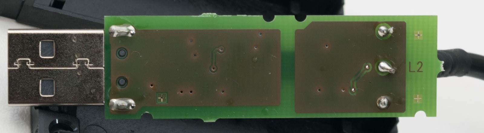
The underside is clear of components but has nice shielding and clear isolation. Because of the design of both the programming adapter and the PLC involving isolation, the design eliminates potential dangers to users and installers.
SmartWire-DT Bus Initialisation
Upon power-on, the controller takes about 10 seconds to fully enumerate and configure the SmartWire-DT bus and then begin running the program. The bus is constantly busy, as if its “busyness” keeps the devices from erroring out as a periodic “heartbeat”. As a result, often the same sequence is sent out quite a few times in duplicate (and removed in the following example).
For my example program during initialisation, we see many of the short commands repeated with longer (presumably configuration/enumeration) strings, sometimes alternating between two patterns:
0x55555555A200B3
0x55555555A200B3DCFE00000000000000000006AA06000001010154D01946
0x55555555A200B3
0x55555555A200B3DCFE00000000000000000006AA050000000101CDC84FC1
0x55555555A200B3680102000000000000000007002700000002DC058313C8AC
0x55555555A20122
0x55555555A2012268000200000000000000000556A700000000250CC1F5
0x55555555A20122
0x55555555A200B3680101000000000000000005B024000001004C28394F
0x55555555A20122
0x55555555A20122680001000000000000000017FAA400000012FEFF735DCE9581D1FF0230000000E703E7031F013A6B
0x55555555A20122
0x55555555A200B368010100000000000000000F5D230000010A0102300000000500010008F126D8
0x55555555A20122
0x55555555A201220000
0x55555555A2012268000100000000000000000505A3000000004E6493A3
0x55555555A20122
0x55555555A200B3DCFE00000000000000000006AA05000000010277994658
0x55555555A20122
0x55555555A200B36802020000000000000000071E2701000002DC059665F3AD
0x55555555A20250
0x55555555A20122
0x55555555A2025068000200000000000000000556A702000000A32E1BFC
0x55555555A20122
0x55555555A200B3680201000000000000000005AE24010001004677C39D
0x55555555A20250
0x55555555A20122
0x55555555A20250680001000000000000000017FAA402000012FEFF735D4EA881D1FF0230000000E703E7034613F1E4
0x55555555A20122
0x55555555A200B368020100000000000000000F43230100010A02023000000006000200A6B2B7E2
0x55555555A20250
0x55555555A20122
0x55555555A2025068000100000000000000000505A302000000C84649AA
0x55555555A20122
0x55555555A200B3680101000000000000000006C2260000000103B5594546
0x55555555A20250
0x55555555A20122
0x55555555A20250
0x55555555A201220000
0x55555555A20250
0x55555555A2012268000100000000000000000505A6000000003EEB736B
0x55555555A20250
0x55555555A200B368010200000000000000000691080000000100E7C44DA3
0x55555555A20250
0x55555555A200B3DCFE00000000000000000006AA050000000103E1A9412F
0x55555555A20250
0x55555555A200B3680302000000000000000007AB2700000002DC05A8EE5B2F
0x55555555A203C1
0x55555555A20250
0x55555555A203C168000200000000000000000556A7000000006CBEC46D
0x55555555A20250
0x55555555A200B36803010000000000000000051B2400000100A659DEE8
0x55555555A203C1
0x55555555A20250
0x55555555A203C1680001000000000000000017FAA400000012FEFFA06DE611811CFF0230000000E703E703F49FDB44
0x55555555A20250
0x55555555A200B368030100000000000000000FF6230000010A030230000000070003008A00ED88
0x55555555A203C1
0x55555555A20250
0x55555555A203C168000100000000000000000505A30000000007D6963B
0x55555555A20250
0x55555555A200B3680201000000000000000006DC260100000103F44A42A6
0x55555555A203C1
0x55555555A20250
0x55555555A203C1
0x55555555A2025068000100000000000000000505A602000000B8C9A962
0x55555555A203C1
0x55555555A200B36802020000000000000000068F080100000100A6D74A43
0x55555555A203C1
0x55555555A200B3DCFE00000000000000000006AA050000000104423C25B1
0x55555555A203C1
0x55555555A200B3680402000000000000000007222701000002DC05B7284DE2
0x55555555A204B4
0x55555555A203C1
0x55555555A204B468000200000000000000000556A702000000F8FCCD60
0x55555555A203C1
0x55555555A200B368040100000000000000000592240100010098074F49
0x55555555A204B4
0x55555555A203C1
0x55555555A204B4680001000000000000000017FAA402000012FEFFA06D7D0C811CFF0230000000E703E7034D55663E
0x55555555A203C1
0x55555555A200B368040100000000000000000F7F230100010A04023000000008000400B8D94FB3
0x55555555A204B4
0x55555555A203C1
0x55555555A204B468000100000000000000000505A30200000093949F36
0x55555555A203C1
0x55555555A200B368030100000000000000000669260000000103A2B53D06
0x55555555A204B4
0x55555555A203C1
0x55555555A204B4
0x55555555A203C168000100000000000000000505A600000000775976F3
0x55555555A204B4
0x55555555A200B36803020000000000000000063A080000000100F02835E3
0x55555555A204B4
0x55555555A200B3DCFE00000000000000000006AA050000000105D40C22C6
0x55555555A204B4
0x55555555A204B4
0x55555555A200B3680502000000000000000007972700000002DC05
0x55555555A204B4
0x55555555A200B3DCFE00000000000000000006AA050000000105D40C22C6
0x55555555A204B4
0x55555555A200B3680502000000000000000007972700000002DC05
0x55555555A204B4
0x55555555A200B3680401000000000000000006E02601000001035739FDC7
0x55555555A204B4
0x55555555A204B468000100000000000000000505A602000000E31B7FFE
0x55555555A204B4
0x55555555A200B3680402000000000000000006B308010000010005A4F522
0x55555555A200B3DCFE00000000000000000006AA060000000108C702073E
0x55555555A200B3DCFE00000000000000000006AA060000000108C702073E
0x55555555A200B3
0x5555555510000000000000000009005B50000000004040454562F5263B
0x5555555510000000000000000009005B400000010140404545064DDA61
0x5555555510000000000000000009005B400000010040404545B664BA5C
It seems that 0x55555555A20 is used as a header during configuration with 0x555555551 used as a header when the bus is operational. Engaging lamp torture, some examples of the bus traffic taken in single snapshot include:
0x5555555510000000000000000009005B40000000004040454513B7E697
0x5555555510000000000000000009005B40000000004040454513B7E697
0x5555555510000000000000000009005B400001010140414545852C6FC6
0x5555555510000000000000000009005B40000100014041454520FF330D
0x5555555510000000000000000009005B40000100014041454520FF330D
0x5555555510000000000000000009005B400000010040404545B664BA5C
Judging from the oscilloscope traces in the main review, the devices are participating in the bus in a “synchronised” fashion with a full message occurring for every PLC “cycle”. There is probably some bit mapping corresponding to I/O bits, in some sense, similar to DMX. At most, there are 83 inputs and 83 outputs in the system, which would correspond to 166 bits, fitting into 21 bytes. The remainder at the end could be a CRC/checksum for transmission error protection to ensure slave transmissions were correctly acknowledged by the master. I’m not sure if there are any asynchronous “push” events possible – I didn’t look into it too closely, but I suspect it to be a master-polled system.