As I continue to evolve my RoadTest procedures, inevitably, some things just don't make it into the original review. Part of this may be due to an abundance of caution in making sure the review is delivered on time, while in other cases, it's purely because I discover something in the process of using the equipment for other tasks. This posting is reserved for discoveries "after the fact" and serves as an addendum to the original review, to be updated whenever new developments are made.
[01/12/2018] Diagnosing Automation Issues with pyvisa
During my review, I preferred to use Python with the pyvisa library working with NI-VISA 18.0 as my preferred automation solution - after all, it's free and familiar, even if it's not the "ideal". Unfortunately, I had issues with command synchronisation that I couldn't adequately resolve for certain tasks which need perfect alignment between command and response. While I was able to some characterisation tasks without issues, the workaround was actually a "retry" mechanism until such time I had some time to investigate it further.
The problems I was encountering were several - namely that I was noticing sometimes there were "buffered" replies if a program crashed midway, such that issuing *IDN? gave the response that was left over in the buffer (e.g. if it was a MEAS:VOLT? then it would be a voltage reading). Another was that when interspersing *OPC? queries into the command stream, I wasn't receiving the '1' I was expecting in return, thus making command synchronisation an issue.
With VISA based devices, generally there are two types of commands. The first is just a "command", which sets a parameter on the instrument. Normally this would be achieved with a command like ins.write('OUTP:GEN 1') and has no returned value. Another type of command is a "query", which ends with a '?'. This asks the instrument for a return value, and can be coded like ins.query('MEAS:VOLT?'), which is equivalent to ins.write('MEAS:VOLT?') followed by an ins.read(). If you issue an ins.read() where no value is forthcoming from the instrument, it usually waits for the time-out period before returning an exception.
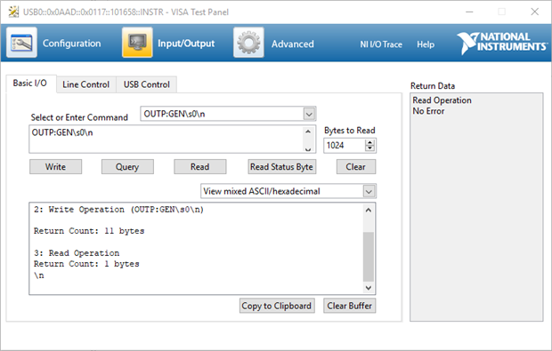
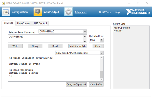
This is when I started teasing at the issue more closely and discovered that the HMP4040.04 behaves differently to most other SCPI-capable instruments I have used. Notice that writing a "setting" command of 'OUTP:GEN 0' results in a read operation that follows it returning a newline character '\n'? This was the issue causing problems with my pyvisa code. As it turns out, it wasn't because I sent the command with a trailing \n either - if you send it without, the same return value is had. However, using the VISA Test Panel seems to show that if you issue a setting command (e.g. 'OUTP:GEN 0') followed by a query command (e.g. *IDN?), the response is correct, namely the IDN string of the instrument.
However, I discovered that pyvisa was a little different. It seems to buffer read replies in a strange way - thus if you issued ins.write('OUTP:GEN 0') followed by ins.query('*IDN?'), you would get the \n instead! I believe that was one reason why my *OPC? commands were causing issues with synchronisation - I used a mixture of write and query. Instead, if we replace all the ins.write with ins.query, the returned '\n' character is "absorbed" and the command synchronisation is retained.
As a result, I've made some small changes to my code that deals with the HMP4040 to first clear the buffer:
print('Clearing Input Buffer of HMP4040 ...')
bufclear = 0
while bufclear==0 :
try :
ins_hmp4040.read();
except :
print('Buffer Cleared!')
bufclear=1;
else :
continue
Basically, this tries to read from the HMP4040 - if that throws an exception (e.g. timeout), then the buffer is empty and we know we're in a good state. From there, all commands including setting commands are sent as queries:
ins_hmp4040.query('OUTP:GEN 0')
ins_hmp4040.query('INST:NSEL 3')
ins_hmp4040.query('OUTP:SEL 1')
ins_hmp4040.query('SOUR:VOLT 10')
ins_hmp4040.query('SOUR:CURR 1')
This seems to do the trick for the most part ... and I thought it was the end of my automation issues until I decided to run an experiment ...
[01/12/2018] Measuring Command Speed Reveals a Surprise!
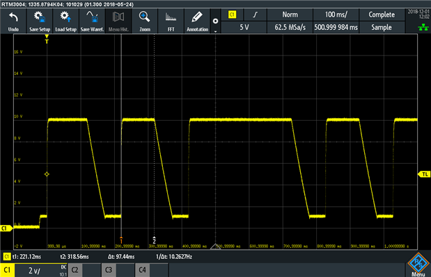
I didn't feel that my use of the scripting within HMExplorer really demonstrated the ability of the HMP4040.04 in terms of its command speed. As a result, I tried to redo the experiment, instead using pyvisa to drive the instrument. The code is called hmpspeed.py and is in the attachment - but basically it toggles the voltage between 10V and 1V repeatedly, using query mode so that an '\n' is read ensuring the command is correctly executed.
Rather surprisingly, a few issues seemed to exist - one is that the command rate was quite "uneven", possibly due to the overhead of Python and USB-TMC bus traffic. The measured period high was about 97.44ms - still not as low as expected. But the code was supposed to cycle the output 100 times, but the measured output did not follow this, suggesting some commands may have dropped or overflowed. I tried to help this by sprinkling *OPC? into the loop, but it didn't seem to make a difference, so it seems rapid-fire no-delay commanding of the HMP4040.04 using pyvisa may be problematic - if there's a secret to this, I don't quite know what it is!
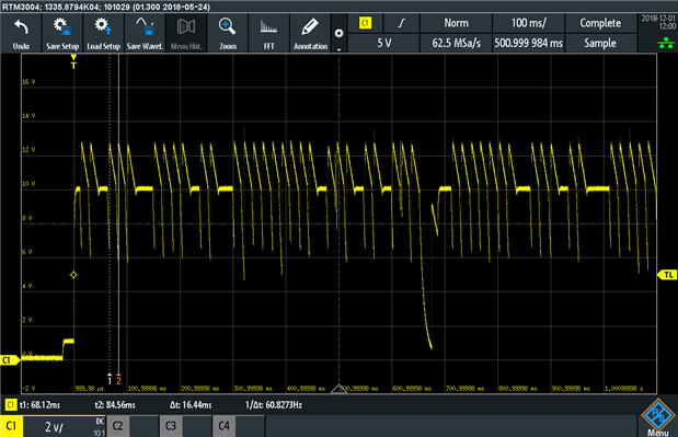
But I thought it might be nice to test a different command - namely toggling the output using 'OUTP:GEN 1' followed by 'OUTP:GEN 0'.
This managed to drive the relays relatively quickly with a loud staccato sound - time between cycles was 16.44ms suggesting that the HMP4040.04 can be very quick with some commands, but now, it seems that repeatedly cycling the output with no load reveals the tendency for overshoot when powering up with capacitors that might still be charged! Now that's an interesting, if not slightly unexpected finding.
[01/12/2018] Characterising an MT3608 Boost-Converter Module
I noticed that some commenters on the original RoadTest posting were looking forward to use of the HMP4040.04 in an automated setting, and I did feel rather guilty that my initial review did not show it in this capacity. This was because of my difficulties with getting reliable command synchronisation from it. Now that I understand that the unit returns '\n' for even setting commands and pyvisa seems to buffer these, I'm back in business with an experiment which I didn't propose in my RoadTest, but thought would be good to do.
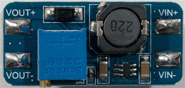
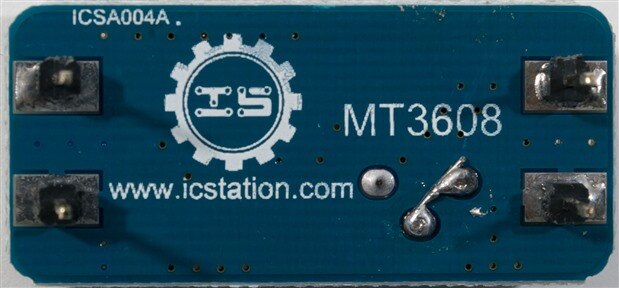
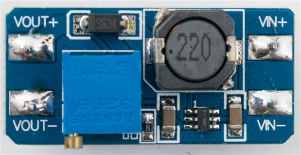
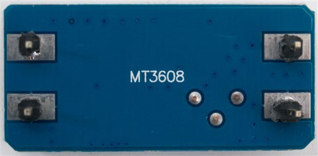
Converting voltages is a common need in many designs, and for rapid prototyping, use of inexpensive modules is very common. In the case of needing a step-up converter, the MT3608 boost converter from ICStation claims to be able to take a 2-24V input and convert it to 2-28V at up to 2A with >93% efficiency provided output voltage is greater than input voltage. This module can be had for around AU$1.10 including postage, so it's quite popular and one I've used before and been quite fond of. In my opinion, it is quite a decent module even with its "counterfeit" Bourns (spelt Bonens) potentiometer.
As a result, I decided to combine the HMP4040.04 with the B&K Precision Model 8600 DC Electronic Load I RoadTested earlier to make an "automated" efficiency data collection system. The script is called autoload.py and basically cycles from a set maximum voltage to a set minimum voltage in set voltage steps. At each voltage step, it cycles the load from minimum current to the maximum current calculated based on total input power available and records all data points into a .csv file. It's not particularly sophisticated, dwelling about 0.5s at each data point (which, in retrospect, may not have been sufficient to settle the converter, resulting in a few anomalies). This resulted in quite a massive data set with some noisy points - so it was filtered where the output of the PSU went CC (to protect the module), when the load was zero and when the output was <95% of the set value (converter instability). If I were to repeat this, I would probably put in some extra readings to perform averaging to get a more stable result.
The good news was that I was able to succeed in running the experiment. The bad news was that the ICStation branded unit (which might have been a copy anyway) managed to smoke quite badly as I had a bug in my code, so I had to test my other batch which seems to be a "generic" clone of the above that is in all ways identical on the PCB except for (possibly) slight variations in the component quality.
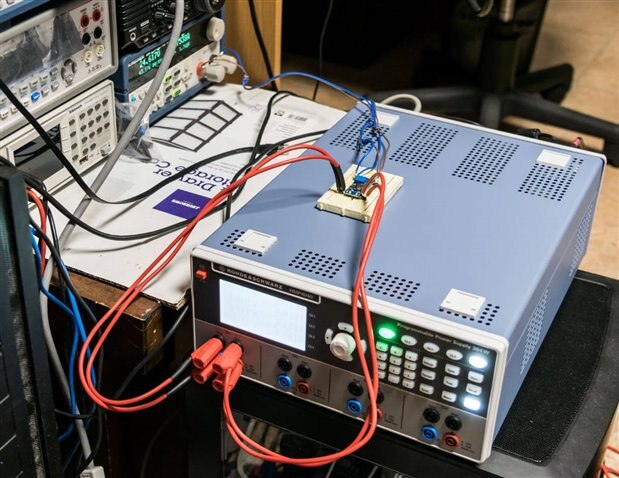
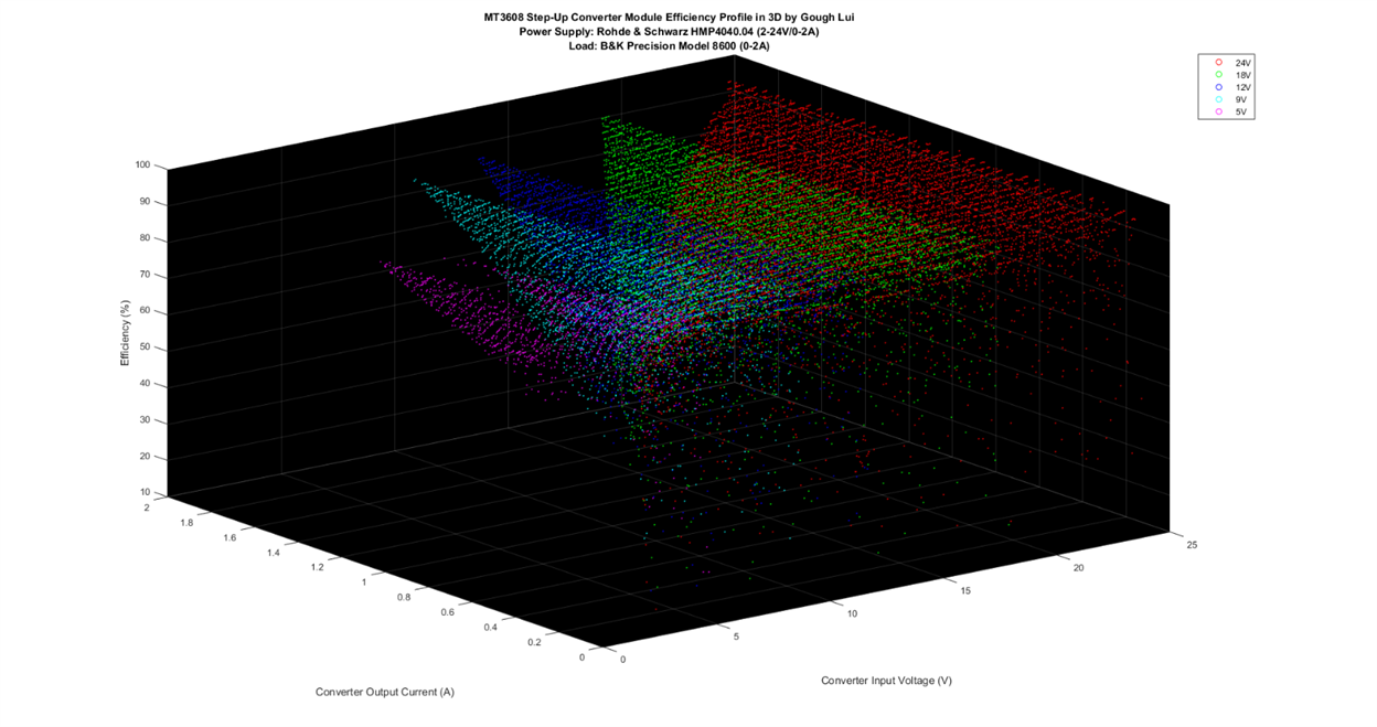
Connections were made with sense at both ends to ensure the converter was as accurately powered and measured as possible. In the case of the "modified" banana test leads - they were all red because element14 somehow had no stock of the black ones locally and I couldn't wait. The result was a set of points plotted on a 3D axis which resemble a "surface", which is quite difficult to interpret at first.
As expected, when the converter is at a low input voltage, or when the load current is small, the efficiency drops off massively and falls into noise as the quiescent current takes over the bulk of the current draw. The shape of the curves represents the power limitation - I take the 2A rating as the maximum current input is 2A (as I've had the chip blow when exceeding this or go into thermal shut-down) which would make sense due to most MOSFETs having an Rds which means heat dissipation is related to current flow. As a result, the greater the voltage difference between input and output voltage, the lower the deliverable current to keep the power in balance (e.g. 12V in at 2A = 24V out at 1A assuming 100% efficiency).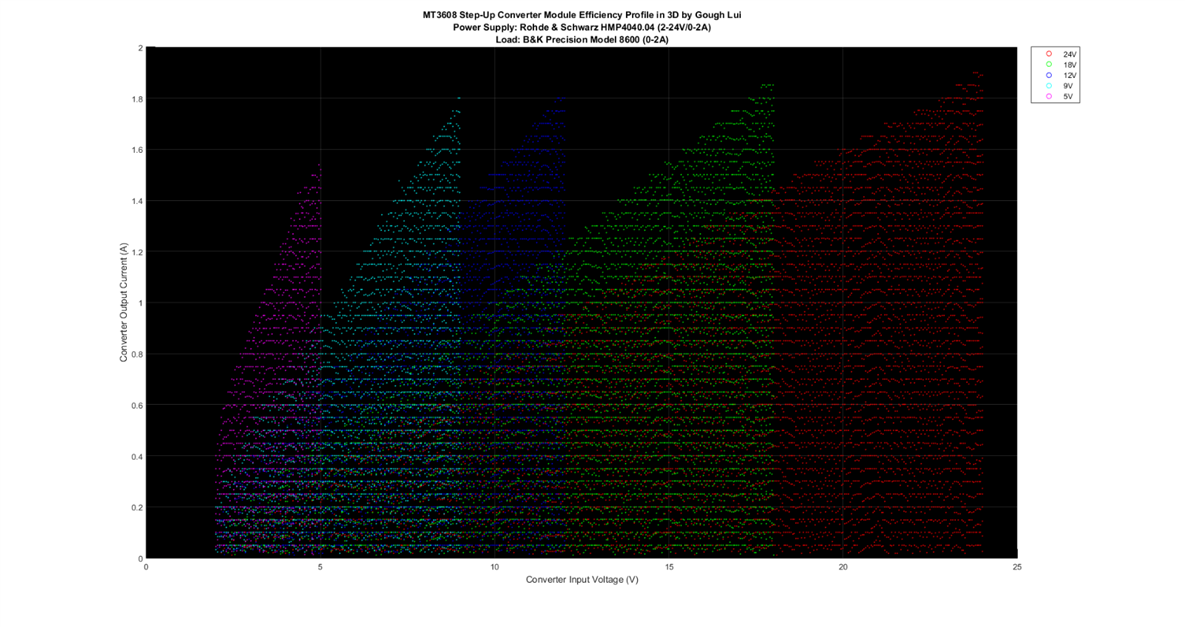
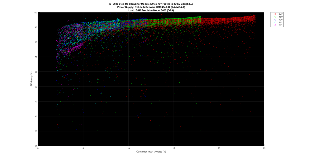
Collapsed into a 2D plot, we see that the converter could maintain voltage at 18/24V to around 1.9A, at 9/12V to about 1.8A and only about 1.5A at 5V before the output voltage fell more than 5%. Because of the 0.05V/A steps, I would expect them to be "gridded" points, but the slight up and down variations represent the "real-life" noise of measurement and the accuracy of both the B&K Model 8600 and the HMP4040.04 are at maintaining their respective load current and input voltage.
Looking at it collapsed into a 2D plot along a different plane, we can see some noise in the values sprinkled everywhere which might be from the low-load data as well as contributions from just random "noise". However, we can see a good "shape" curve start to emerge from the data, with the "thickness" of the band indicating the efficiency variations between zero to maximum load maintaining input current between 0 to 2A. Indeed, rather impressively, quite a lot of the bulk of the curves are maintained above 90% which is a good result, although it seems running the unit with a low input voltage below about 8V costs quite a bit in efficiency, as does choosing low output voltages of 5 or 9V - maybe the rectifying Schottky diode voltage drop starts to be a significant loss at such low voltages making it hard to maintain a high efficiency. Ironically, it seems that it is happiest around 12-18V, whereas the efficiency at 24V seems to be lower throughout the majority possibly signifying the higher voltages inspire more leakage losses.
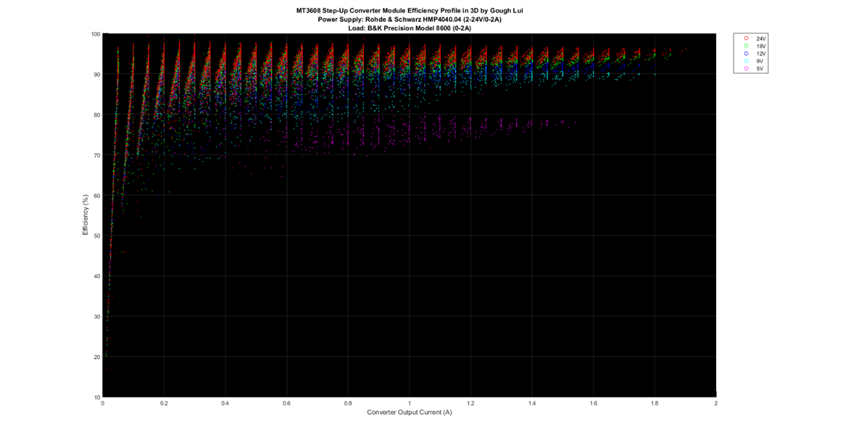
Finally, looking at it as efficiency as a function of converter output current, we see some "slanted" spots because it seems the B&K Model 8600 wasn't quite able to hit its target current exactly or the MT3608 board itself had ripple/response interactions which caused the operating point measured to shift. But in all, it seems that high efficiencies can be reached even at lower currents which suggests a low quiescent current. However, similar voltage trends are apparent - the converter really likes voltages at the higher end of its range with 5V suffering quite significantly.
Testing in such a way doesn't take too much effort as the testing is automated and completed in about 45 minutes at each voltage. The data analysis is a little more manual, and at present, extremely crude - but I can understand why curves are much easier to interpret than "surfaces". The testing suffered from reading noise, so in future, longer dwell times and sample averaging probably can resolve some of this. It didn't also take into account the thermal properties of the converter or the ability to start-up under the given load, nor did it examine ripple and noise. However, it does show the power of using instruments together in an automated testing set-up.
While running this test, I also noticed the toroidal transformer in the HMP4040.04 does make a slight humming at certain loads, and during power-on, the soft start does make it hum a little. At least it's not a loud "thunk" with the associated in-rush current. The HMP4040.04 remained quiet, with the noise of the B&K Model 8600 noticeably louder in comparison.
Hope you enjoyed this update. This post to be updated when further new discoveries are made.
[17/06/2019] Taking the Covers Off!
Seeing as there was no update on the insurance claim on the supply and inspired by the Infineon RoadTest to see if I could reclaim the fourth channel on the supply, I decided to take the supply apart for a Teardown and (Attempted) Repair.
See this post for further details.
[29/06/2019] Error in Current Programming / Readback Graphs Discovered
Two errors were discovered in my review graphs which resulted in the error margins for the current programming and read-back graphs to be incorrect, despite having the correct absolute values. This may have led to misinterpretations, thus I have re-processed the data with the correct error margin values and publish this follow-up. In all, this does not really change the conclusion in any significant way - instead, it shows that the Keithley Model 2110 perhaps doesn't have enough accuracy enough above 3A to be as confident of the results, but the values below 3A and the absolute error still strongly suggest that the supply not only meets the specifications, it beats them by a comfortable margin. It also now reveals that the read-back capabilities of the HMP4040 rival or even beat that of even a 5.5-digit benchtop meter, meaning external instrumentation may not be necessary at all.
I sincerely apologise to Rohde & Schwarz, element14 and all readers for this error on my behalf. I take full responsibility for what has been a rather careless mistake, and I thank you for your continued trust and support.

