


Serial interfaces of a number of types are in common use in embedded systems and having the ability to analyse and troubleshoot these communications in the digital domain is one part of a mixed-domain solution. The RTM3004 has the following protocol decode options for triggering and decoding available as options at the time of writing:
- RTM-K1 for I2C and SPI
- RTM-K2 for UART/RS-232/RS-422/RS-485
- RTM-K3 for CAN and LIN
- RTM-K5 for Audio (I2S, JK, RJ and TDM)
- RTM-K6 for MIL-STD-1553
- RTM-K7 for ARINC 429
As each of these protocols are offered as a separate option, you can buy only the decoders which are useful at the present moment and upgrade later as your needs increase. The most useful are probably I2C, SPI, UART and possibly audio for embedded applications. Those working in automotive development would probably be interested in CAN and LIN. Those working in aeronautical or aerospace development would be interested in MIL-STD-1553 and ARINC 429.
Serial Peripheral Interface (SPI)
The Serial Peripheral Interface (SPI) is a synchronous, four-wire interface, commonly implemented with Master-Out-Slave-In (MOSI), Master-In-Slave-Out (MISO), Serial Clock (SCLK) and Chip Select (CS) with varying polarities for the signals.
Experiment: Arduino microSD Card Initialisation Routine
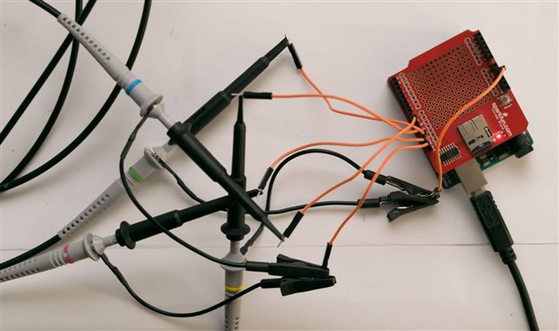
To explore the SPI protocol decode option, I used an Arduino Uno and Sparkfun microSD Shield with the Cardinfo sample code to generate some traffic. This should generate a series of SPI transactions between the Arduino (transmitting at 5V, going through a buffer as a level shifter) and the card (transmitting at 3.3V). All four lines were connected for decoding.
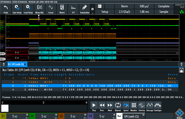
A decode with the unit starting off in the reset state shows the first data burst after a reboot. This appears in the bus table as two lines – one for each direction with a string of bytes sequentially shown, which is truncated.
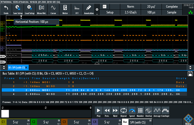
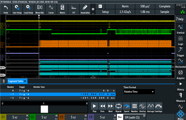
It is possible to zoom into the display and shift the trigger point to see each of the bytes in the comb display. Using the history bar, several bursts can be analysed including a longer bi-directional transaction (note C2 which shows more activity) which is probably reading the file-system on the card.
An issue was identified in saving the bus table of multiple-data-line protocols (e.g. SPI with MOSI and MISO, UART with RXD and TXD) resulting in the oscilloscope locking up. This issue has been reported to Rhode & Schwarz for rectification. Furthermore, the issue in regards to the long data strings from SPI captures being cut-off in the bus table has also been reported for investigation.
Universal Asynchronous Receiver and Transmitter (UART)
The Universal Asynchronous Receiver and Transmitter (UART) is very familiar as the underlying technology behind serial ports on personal computers. This protocol normally uses two wires (excluding handshaking lines) to convey the receive data (RXD) and transmit data (TXD) lines. This is an asynchronous transmission mode requiring no dedicated clock line, instead relying on the presence of start bits and stop bits which add overhead and permit the receivers to synchronise with the signal from the sender.
Experiment: UART Capture Dead-Time
I decided to try and kill a few birds with one stone in this experiment – I was interested in what the maximum UART rate of an Arduino Uno was, whether the RTM3004 would work with fairly custom UART rates and what the “dead-time” or “blind-time” between acquisitions is. This is important especially for long or continuous data-streams where data can be lost between the memory buffer filling and the next trigger happens.
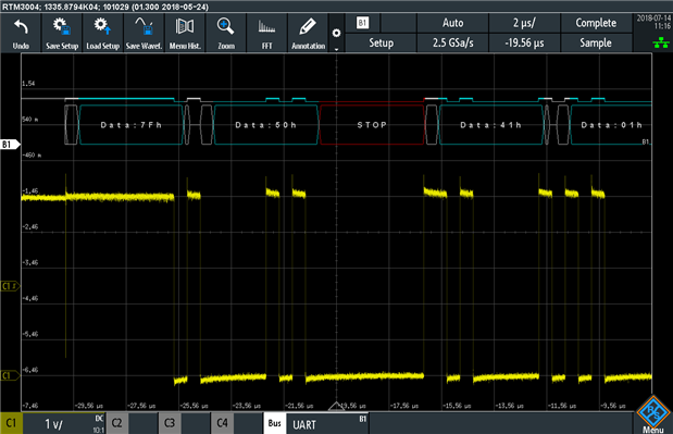
To do this, I programmed a simple program that constantly emits easily recognisable character sequences at the maximum rate the Arduino Uno is capable of which is 2Mbit/s. The sequences basically run as a pair of bytes – the first starts at A followed by a second byte which goes from 0x00 through to 0xFF. Then the first byte is incremented to a B, and this is repeated until we reach Z followed by 0xFF, which rolls back to an A. For more details, see Appendix. The trigger was set to serial trigger and fast segmentation was enabled.
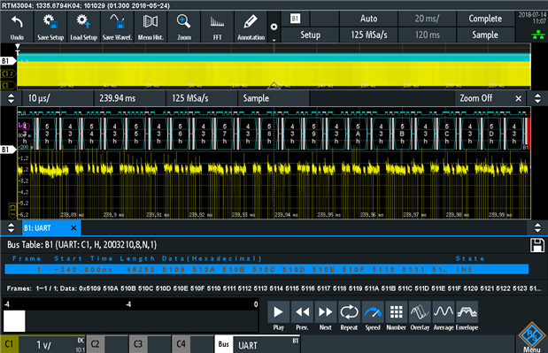
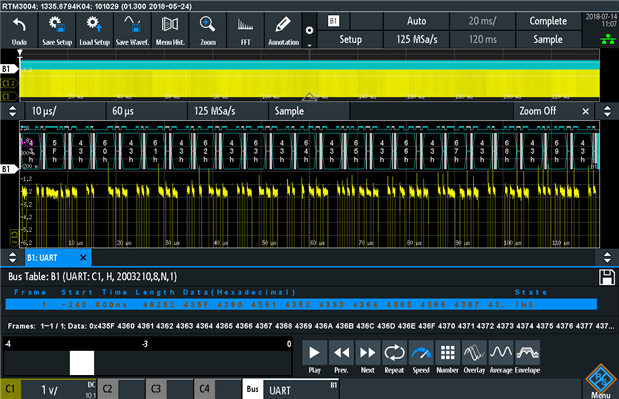
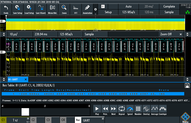
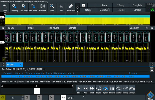
It was determined that the dead-time was effectively almost zero, with part of the last byte in each capture “broken” but the next segment starting at the beginning of the byte that followed – e.g. 0x43 0x5D, 0x43 (broken between buffers), 0x43 0x5F in the first pair and 0x4F 0xB3, 0x4F (broken between buffers), 0x4F 0xB5. The only byte lost was the byte broken in-between buffers, which is good news.
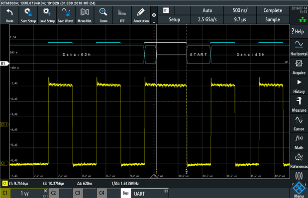
Most people have mentioned that the AVR isn’t really capable of doing the processing necessary to make proper use of the 2Mbit/s bit rate. While I’d be inclined to agree in some degree, this trivial program showed that the latency between emitted bytes only about 620ns.
An issue was detected where a false start condition was detected on a short glitch of the input, too short to be a reasonable start bit. I have suggested to Rohde & Schwarz that maybe some filtering of the pulse widths is necessary to determine whether it is an intentional “bit” or glitch to avoid the decode window being opened early as in this case.
Inter-Integrated Circuit (I2C)
Inter-Integrated Circuit (I2C) is a two-wire interface which is commonly used between ICs within a device. This uses two lines, the serial clock (SCL) and serial data (SDA) lines, which operate at speeds of 100khz, 400khz, 1Mhz, 3.4Mhz or 5Mhz and is shared between a number of devices.
Experiment: Bosch BMP280 Sensor I2C Analysis
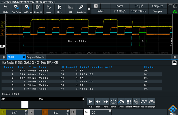
To test I2C decoding, I decided to co-opt a little project I’ve been building just for fun which uses a Bosch BMP280 sensor with the Adafruit library. This project basically just periodically reads the temperature and the barometric pressure from the sensor, resulting in an intermittent stream of I2C traffic which can be analysed.
With a few frames captured into the fast segmentation memory and analysed, a few timing variations between requests are visible, along with the changing values due to changes in physical parameters. The decode itself is colourful, indicating clearly which is the device address, register, access type and acknowledgement status. In fact, we can see that the first two transactions are usually the same, which indicates to me that there’s an inefficiency I can probably “code away” – requesting the barometric pressure actually requests the temperature as well (it seems). Because I had adjusted the time base and record length, it was possible to fit 213 records into the segmented memory, triggering just once every time the three I2C transactions were being run (once a second). This allowed for monitoring over the space of around three and a half minutes of values.
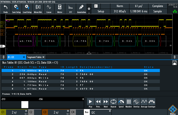
This is more clearly illustrated if I zoom in on just one transaction. I find that the labelling is very clear and easy to understand and unlike the SPI example, the bus table decode is very well presented due to the brevity of the transactions.
While reading about other people’s experiences with I2C debugging, I came across a discussion mentioning something termed an “ACK spike” by some people. This is a short transient glitch in-between when the sender “releases” the bus and the receiver “drives” the bus to acknowledge the transaction. It was good to see it for myself on the oscilloscope.
Experiment: Mixed I2C and UART Decoding of ESP8266 AT-Command Project
Well, the project involving the Bosch BMP280 actually involves an Arduino Pro Mini and an ESP8266 ESP-01 Module in AT Command Mode. The project basically reads the sensor and assembles a text string which is sent to the ESP8266 to send as a broadcast UDP packet. This provides a perfect opportunity to demonstrate the ability of the RTM3004 to perform multiple bus decodes in parallel. The RTM3004 offers four slots for decoding, but it’s important to remember that some modes require the use of two slots (e.g. UART with both RXD and TXD lines). This can be extremely useful when debugging unusual behaviour – e.g. was the sensor at fault? translation code? Wi-Fi module? etc.
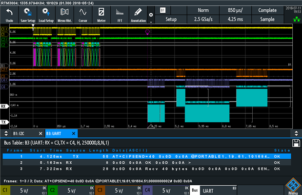
It is possible to use a single capture to catch the I2C read from the sensor, perform the conversions and then send the necessary AT commands to the module to send the result. The UART link is operating at 250kbit/s, another custom rate which seemed to work without a hitch.
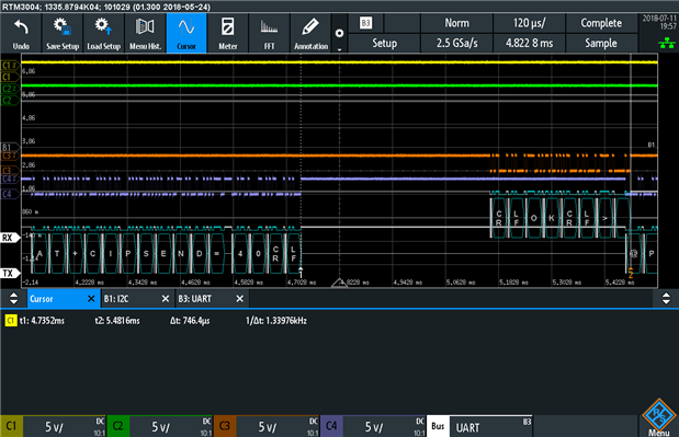
The labels inside the comb display can be changed to ASCII which makes interpretation of the data very easy. A slight violation is seen in timing, as I begin sending the data packet as soon as I receive “OK” from the module – but the module hasn’t finished sending its response. It doesn’t seem this causes any harm though. The turn-around from sending the command to send a 40-byte message to when the ESP8266 is ready to receive it is 746.4us.
It is possible to trigger on byte sequences up to three bytes long, so alternatively rather than triggering on a start-bit, I could have triggered on “AT+” so as to monitor every single request to the ESP8266 in AT Command Mode. As I realised it was a little wasteful to use an Arduino and an ESP8266 in AT Command Mode, I refactored the project to use ESP8266 Arduino Core to do the same thing but more efficiently. But then I wouldn’t be able to show off the mixed protocol decode feature …
Conclusion
I was able to evaluate the protocol decoding for SPI, UART and I2C as these are common interfaces which can easily be encountered in simple microcontroller-based embedded systems. Setup and decoding was straightforward, with the ability to display the decoded data in bus table and on-trace comb style display. Triggering worked positively, as did warnings of data aliasing at low sample rates and deep memory history mode for recording infrequent bursts of data on the bus. Custom data rates for UART of 250kbit/s and 2Mbit/s were tested without difficulty although the actual rate did vary slightly from the set rate. It was determined that the between-sample dead time is practically zero when operating in the fast segmented memory mode. Mixed protocol decoding was also demonstrated, with some limitations due to certain protocols requiring the use of two of the four available decoder slots to cover RXD and TXD or MOSI and MISO. Issues found include long data lines in the bus table for SPI being “cut off”, glitches causing false detection of a start bit with UART decodes and with saving the bus table for protocols with multiple data lines –issues which have been reported.
While the RTM3004 does have the ability to generate demonstration signals for the other types of buses through the pattern generator or arbitrary waveform generator, I did not use them as I felt this would be somewhat unrealistic. However, given that the features offered by most protocol decoding options are fairly similar, I feel that this is not a major omission.
Depending on your application, obtaining the appropriate protocol decoder options would be recommended. However, it is worth keeping in mind that the RTM3004 offers a more limited protocol decode option set compared to some of its competitors, so if it is necessary to decode protocols not in the options list, it may be worthwhile looking at alternatives.