


The RTM3004 can be more than just an oscilloscope. With the addition of the RTM-B6 Waveform Generator and 4-bit Pattern Generator option, it’s possible to generate regular functions, modulated functions, bit patterns and arbitrary waveforms for testing devices from the oscilloscope itself.
Pattern Generator
The RTM3004’s 4-bit pattern generator is output from four lugs on the front panel. This is not the most convenient form of connectivity if you’re looking to drive an external circuit, but at least it can be used easily for demonstration purposes. The pattern generator can generate a range of patterns including Square Wave, Counter, Arbitrary (sequence), Manual (fixed value), UART, SPI, I2C, CAN, LIN, Audio – I2S and Audio – TDM. Only one pattern can be generated at any time, with some patterns only making use of a few of the outputs. The output voltage ranges from 1.5V to 3.3V, with serial output bitrates from 9600bps to 1Mbit/s. For the included serial modes, the serial data is fixed as random.

The arbitrary setting provides the possibility from defining a pattern up to 8192 points long across all four outputs, allowing for simulation of other signals. Each of the points are replayed at a constant rate with an idle time of 50ns to 1s, or 1Hz to 20Mhz.

The most basic demo is just that of the counter, which uses all four outputs. The signals look a little wavy on screen, probably due to using the “long” ground clip leads. However, I’d have to say that as a basic pattern generator, it seems perfectly serviceable.

Function Generator
A separate BNC connection on the front panel provides the output from the inbuilt generator which can perform function generator tasks. This includes producing modulated functions with AM, FM, ASK and FSK modulations with variable modulation depth/shift frequency and a fixed modulation input frequency. The generator is switchable between High-Z and 50-ohm modes, with voltages of either 20mV to 10V peak-to-peak for High-Z and 10mV to 5V peak-to-peak for 50 ohm. Output resolution is claimed to be 14-bit at 250Msample/s
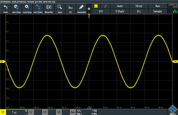
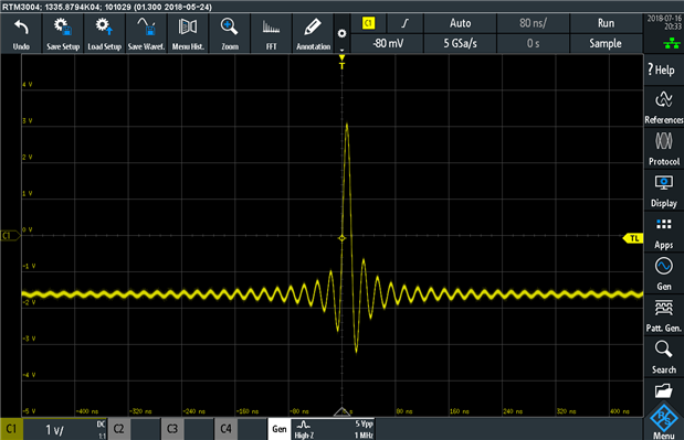
Inbuilt functions include Sine (0.1-25Mhz), Pulse, Rectangle (0.1-10Mhz), Ramp, Triangle, Sinc and Exponential (0.1 to 1Mhz). Noise can be added up to 100% of signal amplitude, with a bandwidth up to 25Mhz.


A sweep mode is also available with a sweep time of 1ms to 10s and sweep type of linear or logarithmic. Modulation of AM, FM, ASK and FSK are available with a frequency between 0.1Hz to 1Mhz.
Experiment: Opamp Gain Transfer Function
Seeing as I have access to an oscilloscope and a signal generator, I decided I would use it to perform a “classic” analog electronics lab experiment, namely that of measuring opamp transfer function. To make things simple, I decided to use the FFT mode display, swept input at a rate of 10s and maximum hold plotting so that I could “build” the graph over time as the frequency was swept.
Because I was using rail-to-rail opamps with a single-ended 0-5V USB supply, I decided to set the generator offset to 2.5V to ensure no saturation would take place. The opamps were configured as voltage followers (unity gain) for simplicity and predictability. The particular opamps used were the Microchip MCP6273 with a 2Mhz gain bandwidth product (GBP) and a Texas Instruments TL974 with a 12Mhz GBP.
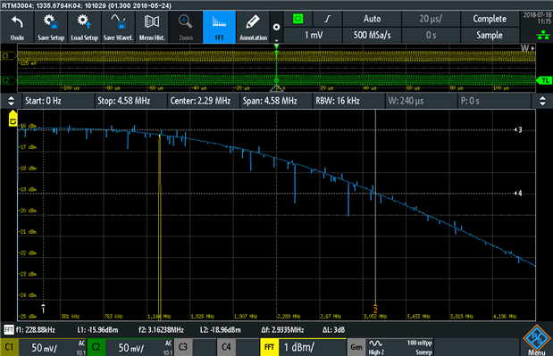
I started with a 1V peak-to-peak input into the MCP6273 and noticed that the FFT result can be plotted in different modes. I tried Veff which plots in against linear voltage. Below the 381khz grid line, it shows the opamp to be fairly flat around 360mV. As this will be the RMS amplitude, this is the expected result which is good (1V peak to peak = 0.5V amplitude * 0.707 = 353mV). But wait a sec … the gain starts falling off at 381khz?

The FFT output can be plotted as a more conventional dBm (power) scale which helps to compare values which range over a large scale. I know this is probably not the best scale to use but it works and it shows that the 3dB drop-off sits about 648.5khz. That’s still not quite what I was expecting.

I changed the generator output to 100mV and things looked much better. The 3dB point was now almost 3Mhz (better than expected).
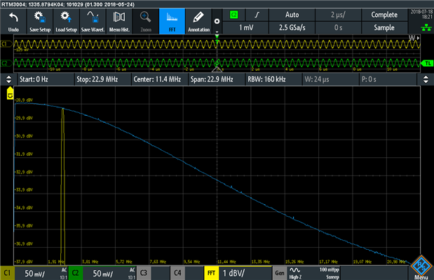
Doing the same with the TL974, I noticed that the gain bandwidth was wider as expected, this time using the dBV scale (the other scale available). But at 1V peak-to-peak, the drop-off occurred around 1.91Mhz.

Changing to 100mV pushed the 3dB point to about 8.5Mhz and 6dB to about 14.5Mhz which is much more in line with expectations.
But why? Remember that an op-amp can be slew-rate limited. As a result, it just can’t keep up with the rate of the incoming signal, producing a “triangle” wave output of much lower amplitude.

Having the function generator and oscilloscope in one really makes it easier to set up these experiments, easier to manipulate the parameters without co-ordinating different pieces of equipment and better in case you are working remotely. There are some limitations in the ability of the hardware, but it is good enough for many basic experiments and of great utility especially in educational contexts.
Note that during these experiments, a bug was found in the X and Y cursor behaviour on FFT traces which results in the L2 and ΔL values not being updated as the cursors were being moved. A workaround consisting of toggling the cursor data source results in the values being correctly recalculated. This issue has been reported to Rohde & Schwarz for future rectification.
Experiment: A Radio Station
It occurred to me, with the modulation available, it is possible to use the RTM3004 to generate signals that could be received on a radio receiver. To do this, I chose an empty portion of the AM band (due to maximum frequency limitations on the generator) at 911khz. The only exception was for FM, due to spectral width, I chose to use the ISM band also used for NFC cards at 13.56Mhz to ensure no interference with licensed services. The signal was received using my Winradio G31DDC software-defined radio. The generator output was attached to a piece of loose wire.


Signals were successfully broadcast and received in AM with 1khz tone, ASK with 440Hz modulation, FM with 1khz tone and 5khz deviation, and FSK at 2Hz with a 500Hz shift frequency. This is illustrated in the waterfall diagrams above.
Unfortunately, as the modulation is not flexible enough to accept an input for modulating the generated function, it is only possible to transmit tones.
Arbitrary Waveform Generator
The arbitrary waveform generator uses the same BNC output and can generate signals at a rate of 10Msamples/sec with a memory depth of 32,000 points. While this isn’t class-leading compared to standalone dedicated instruments, it is still enough to be quite useful and the integration with the RTM3004 is of value.
Experiment: Arbitrary Waveform Graphics
This led me to some shower-time thinking – just how arbitrary can a waveform get and how can I demonstrate its capabilities? I was convinced there was a way to draw an image with it and before long, I was able to do exactly that. If you’re interested in knowing how it was done, look at the Appendix post where I discuss that.
But what would be a good image to draw? I know, how about an image that expresses my gratitude?

That was the arbitrary waveform generator looped back into C2 (because I like green). Don’t believe me?

Seeing as I’ve gone so far, I thought I’d let the oscilloscope advertise itself.

If you’d like to try this for yourself, the CSV files that generate the images are also attached to this post – import them as a reference waveform, select it as the source for the arbitrary waveform generator, loop the input back, turn on dot-mode display (as opposed to lines), get the trigger set up just right and see for yourself.
As demonstrated, the arbitrary waveform generator is quite useful for generating any sort of analog signal within its capabilities for test purposes. While its memory depth and signal frequency doesn’t match some stand-alone units, there is a convenience of integration for all-in-one automated testing and not consuming additional bench-space.
Conclusion
The option provides a basic 4-bit pattern generator with a number of inbuilt random-data serial protocol options, counter and arbitrary pattern capability up to 8192 points with a rate up to 20Mhz and output voltage between 1.5V to 3.3V. While this can be useful for demonstration purposes, its output being connected to four lugs on the front panel makes it inconvenient for other uses.
The function generator is capable of generating Sine (0.1-25Mhz), Pulse, Rectangle (0.1-10Mhz), Ramp, Triangle, Sinc and Exponential (0.1 to 1Mhz). with noise (0-100%) and AM/FM/ASK/FSK modulation ability with variable modulation depth/shift frequency and a fixed modulation input frequency.
The arbitrary waveform generator is capable of providing up to 10Msample/s rates for up to 32,000 memory points and output voltages either 20mV to 10V peak-to-peak for High-Z and 10mV to 5V peak-to-peak for 50 ohm.
In all cases, the parameters for these features are not class-leading when compared to dedicated standalone instruments. However, despite this, the option does provide enough performance for many tasks. Its main advantage is the fact it is already integrated into the RTM3004, making it easier to set-up and control remotely, while taking no extra bench space or power points. If the specifications meet your needs, the RTM-B6 Waveform Generator and 4-bit Pattern Generator option could be well worth having.
Top Comments