


Now that I have the Tektronix 2-series MSO in-hand, it’s time to set it up and find out what it’s like to live with. Unfortunately, as this unit has not been provided with the 16-channel digital probe, there will be no tests involving the digital channels. As this particular blog is going to be quite long, I’ve broken it into sections and a table of contents is provided below:
Table of Contents
Initial Set-Up
Getting the 2-series MSO ready for use is more than just unboxing the unit and plugging it in. There is an included guide which I followed to get the most out of it.
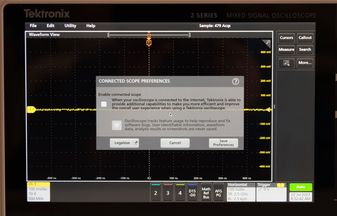
Of course, I did plug it in and turn it on and it asked me whether I wanted to enable the “connected scope” features and tracking features. I decided to enable the former but not the latter.
Firmware Update
The 2-series MSO initially shipped with an older version of firmware (v1.46.18.839) while the current version is V2.2.6.1052. As a result, I decided to follow the instructions and update the firmware, which involves using a USB flash drive and unzipping firmware.img into the root directory and rebooting the oscilloscope. The firmware update process went seamlessly and the visuals during the upgrade were quite clear about what was happening.

After rebooting, the firmware version is verified in the “About” screen, along with the 2-DDU time-limited license. It should be noted that the promised “for the future” Digital VoltMeter (DVM) and Frequency Counter features in the datasheet don’t appear to be in this update yet (or I can’t find them).
Being a little curious, I decided to examine the firmware.img file to learn more about the MSO24. As it turns out, it’s a nest of .tar.gz files along with a signature file to prevent tampering. The contents of the firmware tell us that the oscilloscope is codenamed “Lexington” and is based around a ZynqMP SoC running PetaLinux with a root user. The unit has a Goodix capacitive touch screen controller and a number of chips including si570, si5324, pca953x, tps65086, ina2xx, tps65086, at24/25, jesd204b, bq32k and max310x. Software-wise, it has Python 2.7 and 3.7, pyvisa and x11vnc. The main application is called “scopeapp” and quite a lot of the observed behaviour of the review can be traced back to the way certain scripts are coded. There are certain exceptions for various revisions of Lexington hardware which seems to be detected by MAC address. I also found files for e*Scope feature, which is not enabled for the MSO24 (see Chapter 4).
Self Test/Signal Path Compensation
On each boot-up, the MSO24 performs a self test. The self test can also be manually initiated through the menus.
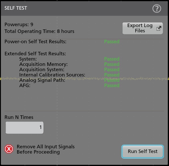
A more thorough procedure can be run that will perform signal path compensation to compensate for DC offsets.
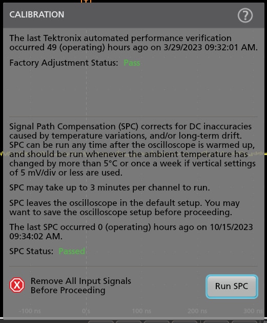
This process takes a considerable amount of time, but completed successfully, indicating that the hardware is good and that it is aligned to produce optimal quality measurements. It is recommended to complete this after each firmware update.
Timezone Setting
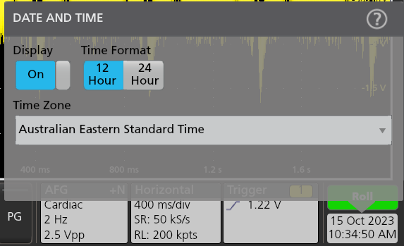
Another important setting is the time-zone setting. It seems the unit automatically sets its time from the network, but needs the time zone to be manually configured. This can be accessed via the clock in the bottom right of the screen.
Probe Compensation
I decided to use the included P6139B 500MHz 10:1 probes with the MSO24, so I fitted them each with identifying colour rings to pair them with a channel. The flat-bladed tool was used to adjust the trimming capacitor to ensure correct probe compensation while being fed by the 1kHz square-wave probe compensation port. This is so that the probe does not distort the signal.

With this, the oscilloscope is now ready to be used and reviewed.
User Experience Thoughts
This section will overview some of the key features of the user experience and will contain my opinions, as an experienced user of oscilloscopes of many types (touch and non-touch) from a number of vendors. I am new to the Tektronix “series” oscilloscope’s touch interface, only having used it briefly during a roadshow demonstration event.
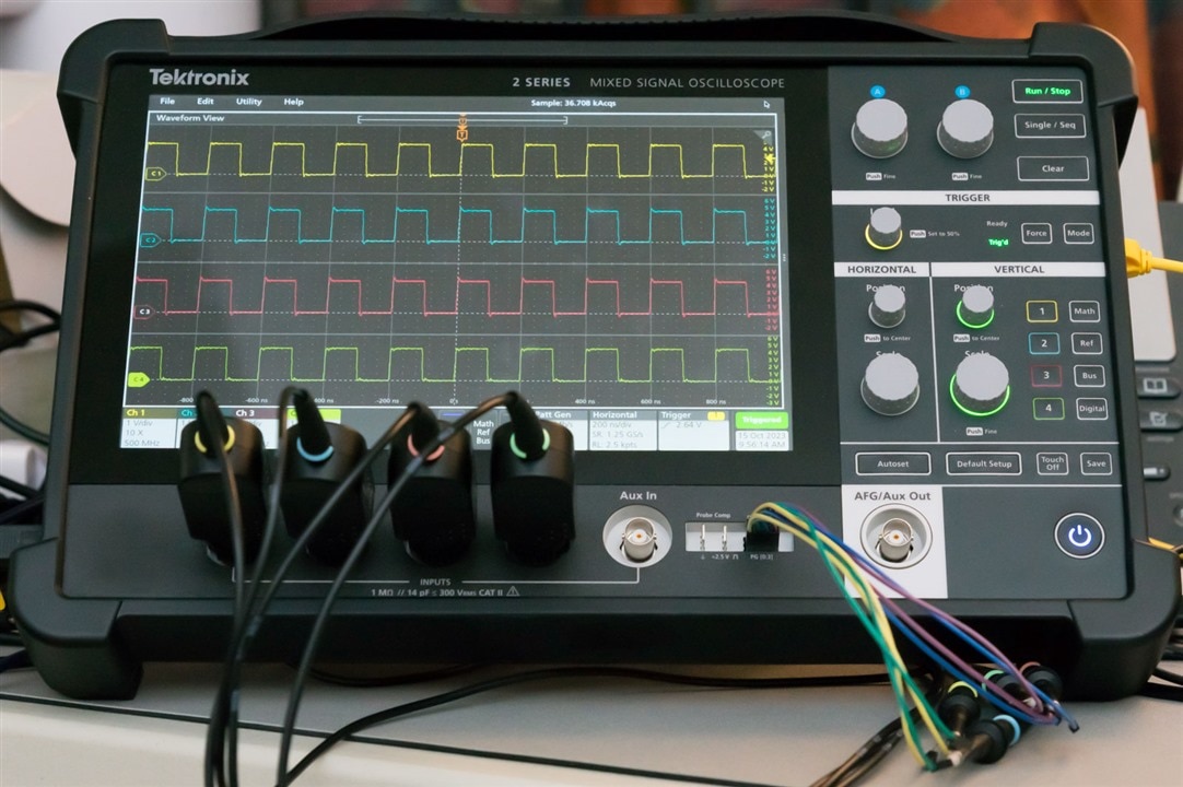
The Mechanical User Interface
The majority of the front of the unit is occupied by a 10.1” touch-screen LCD by which most interactions take place. The screen itself has good resolution at 1280x800, matching that of the Rohde & Schwarz RTM3004 I reviewed in previous years and is the best amongst portables. Brightness and contrast seem adequate for indoor usage, however, I can foresee that even at the “High” backlight setting, it could become difficult to read outdoors. Perhaps the biggest downside is the glossy surface finish which does an excellent job of causing glare reflections. A matte finish would help significantly.
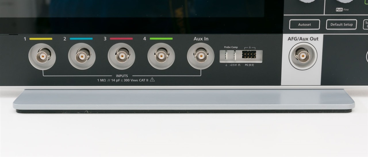
The BNC input and output jacks are below the screen, along with the pattern generator and probe compensation outputs. This arrangement is traditional, however, it should be noted that the probe interfaces are “plain” BNC with no support for TekVPI or FlexChannel interfaces. It doesn’t even have an additional ground ring for the “pin” on the P6139B probes to contact.
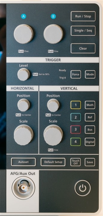
The buttons themselves are a departure from most oscilloscopes which feature squishy, rubber keypads. The buttons on the 2-series MSO are a membrane keypad, with a tactile snap action and LED illumination through selected buttons. This has much shorter travel and less tactile definition on button edges. Sometimes, it feels a little bit like using a microwave oven and the thought runs through my head as to whether I should be using my fingernails on it, as it may be a little more fragile. The advantage would be that such buttons are easier to wipe down and clean with fewer gaps and grooves where dirt can collect, although I suspect the reduced depth requirement was another reason for choosing this technology. It is noted that the (software) power button is located on the bottom right, while I am used to the power buttons being in the bottom left, so often I end up “feeling” the button-less area on the left side looking for a button that isn’t there! I’m sure I’ll get used to this after a bit …
The knobs on the unit rotate and “click” as you would expect, with some being lit by LED lights to indicate the selected channel for which the knob would take effect. This is all relatively standard for modern touch-screen oscilloscopes. However, the presence of knobs with the gaps between the knob and body suggest that the surface should be kept clean as it is not officially ingress-protected.
The arrangement of the buttons and knobs are well-grouped and clearly presented. The presence of an A and B multi-function knob is a point of contrast as some other vendors have just one such knob.
When using the unit on battery, it is necessary to attach a ground cable to the grounding screw on the side of the unit whenever any voltage greater than low-voltage is present for operator safety. When operating from mains power, the ground connection is taken from the power supply automatically. This is a unique consideration that may explain why the power input is from a special power supply rather than the more ubiquitous USB-C PD as power quality and grounding cannot be assured.
The Software User Interface
The user interface itself seemed pretty neat at first glance, but is very grey. There is much more than meets the eye because of its design, which does take a little bit of practice to get used to.
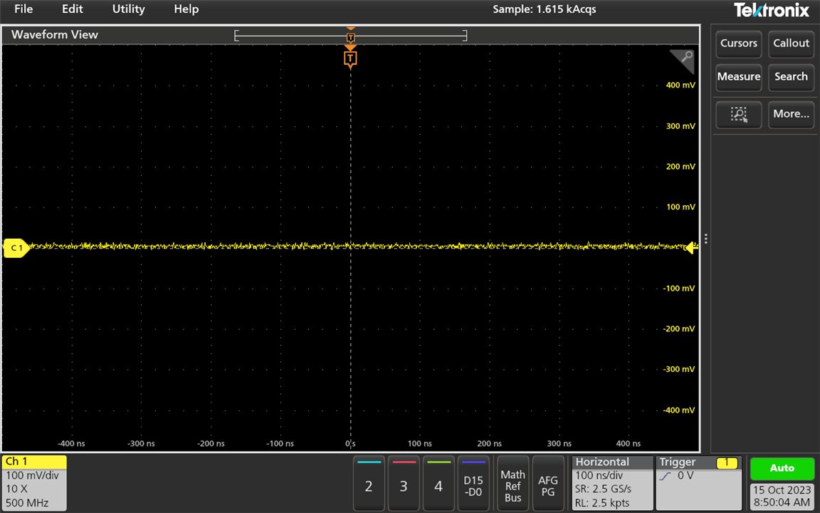
By default, the user interface looks like this with the waveform view occupying most of the space. There is a toolbar to the bottom which is permanent, and one to the right which is collapsible. A menu bar stretches across the top.

The menu bar allows for access to key configuration features which is similar to the UI that can be found on a computer program.

Some of these menus bring up a “flip menu” which is analogous to a menu with multiple tabs.
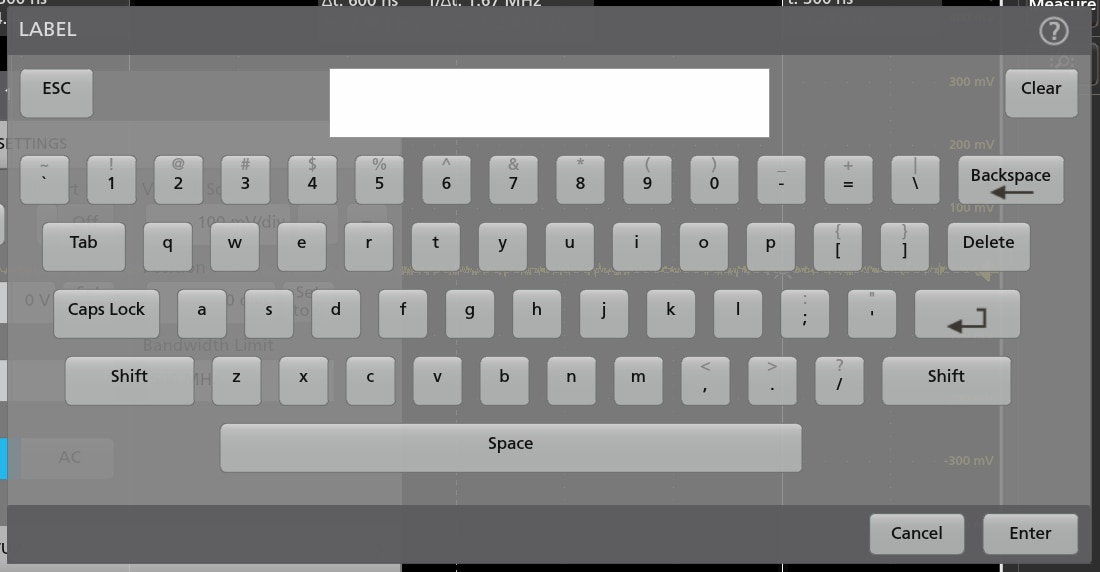

Depending on the entry required, on-screen keyboards and keypads are available to enter data. Alternatively, a USB-connected mouse and/or keyboard can be used to interact with these menus. The size of the touch targets are quite appropriate and easy to use.
![]()
![]()
The bottom toolbar revolves around badges that control the status of channels and functions. Badges, when tapped, can expand to provide buttons to change scale. In the case of other badges with multiple functions, they expose a nest of additional badges. To disable or remove channels requires “flicking” the badge off the screen which was not an intuitive movement at first.
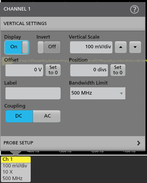
Tapping on badges again will bring up the menu for configuring that channel.
It is also noted that the right-side toolbar that is collapsible is home to measurement badges which operate similarly to the channel badges – tap for more configuration menus, flick off the screen to dismiss. The right-side toolbar is also home to measurement, mask test, zoom, search and annotation functions.

The “More…” button exposes the dual-function of the button next to it, which can be used to define a zoom area or a mask.

For example, defining masks graphically in the Mask Test tool exposes various additional capabilities (move, resize, redefine vertices, rotate) when the mask is tapped. Such functionality could easily be missed.
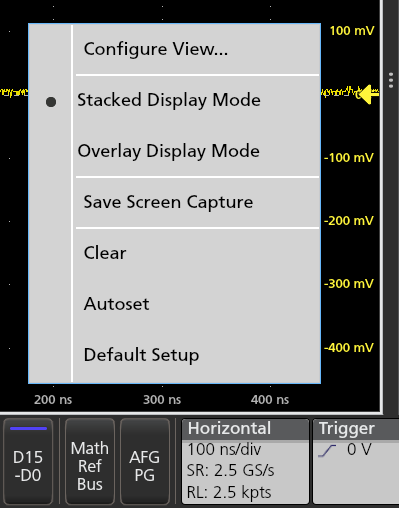
Perhaps less obvious are the menu options which can be hidden in “right click” (or long-touch) menus. There are other features which may require judicious tapping on the screen.

I do like the fact that, given enough desire, it is possible to take things to the extreme and rearrange the view - overlay the traces, reduce the font size and have multiple windows tiled to your preferences.
While the UI seems easy enough to work with, I do occasionally need to think twice about how to access a certain feature as there’s not one “centralised” means to get to the function – it could be in the toolbar, in a badge, in a button on the side-bar, hidden in a right-click menu, or nested behind multiple badges/menus. I guess this is something that users will get familiarised with over time, but for new users to the UI, a search feature could help.
Other Functionality Walkthrough
In this sub-section, I will introduce some of the other features.
The oscilloscope’s “Save As” menu provides the ability to save screenshots, waveforms, settings, reports and sessions in various formats.

Rather than needing to go through the menus, the save button on the front panel can be used to save screenshots – once first configured, subsequent presses will perform the action and provide a confirmation dialog.

There is some onboard storage available, but the use of TekDrive, network share and USB memory devices is possible (see Chapter 4).
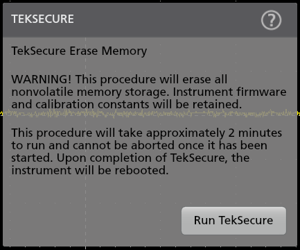
Storage devices can be sanitised through running TekSecure from the menu. This will perform a zero-overwrite of the storage areas.
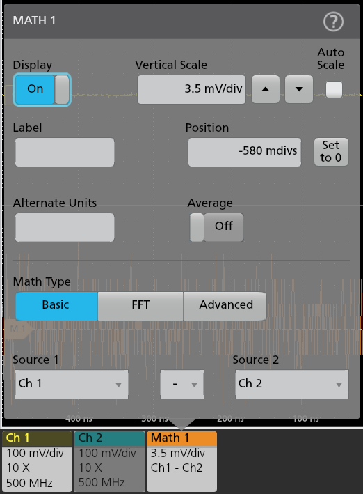
The Math menu allows access to FFT functions and basic math features.

The advanced menu provides an on-screen equation editor to construct more sophisticated equations. The unit also allows for loading of an “unlimited” number of reference waveforms, subject to system memory.
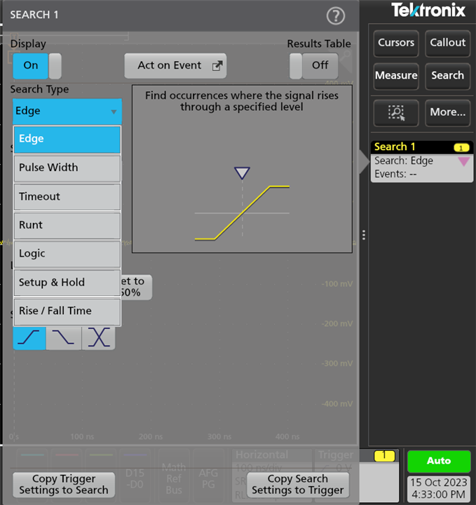
The search feature allows for looking for triggerable events within a waveform.


Mask tests can be defined by segments or by waveform tolerance methods, with the ability to save masks to .xml files.
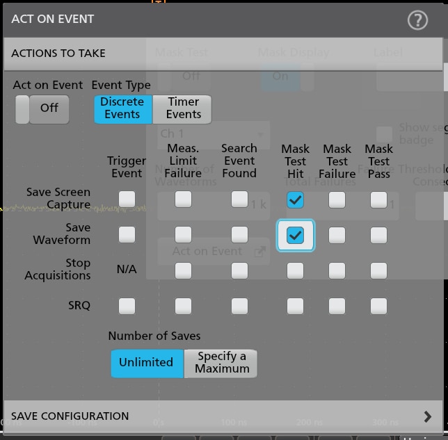
When events occur, it is possible to perform actions such as saving a screen capture, waveform, stopping acquisition or raising a service request (SRQ).
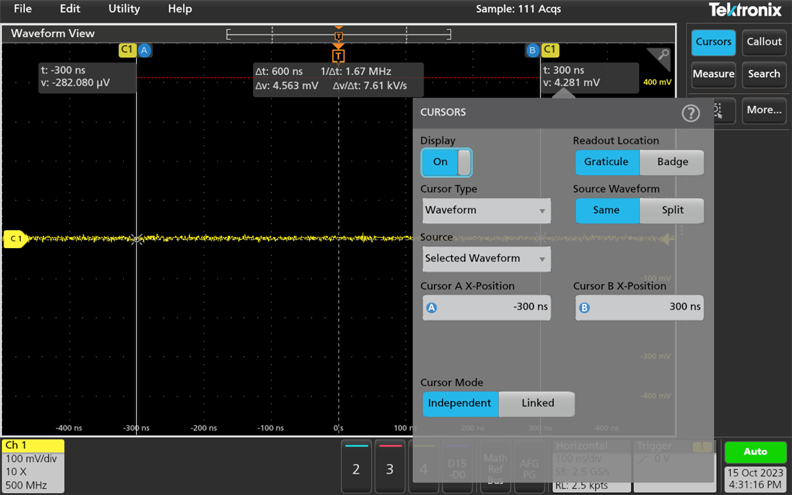
Measurement cursors can be configured and the two multi-function knobs can be used to independently adjust them, which is quite nifty.
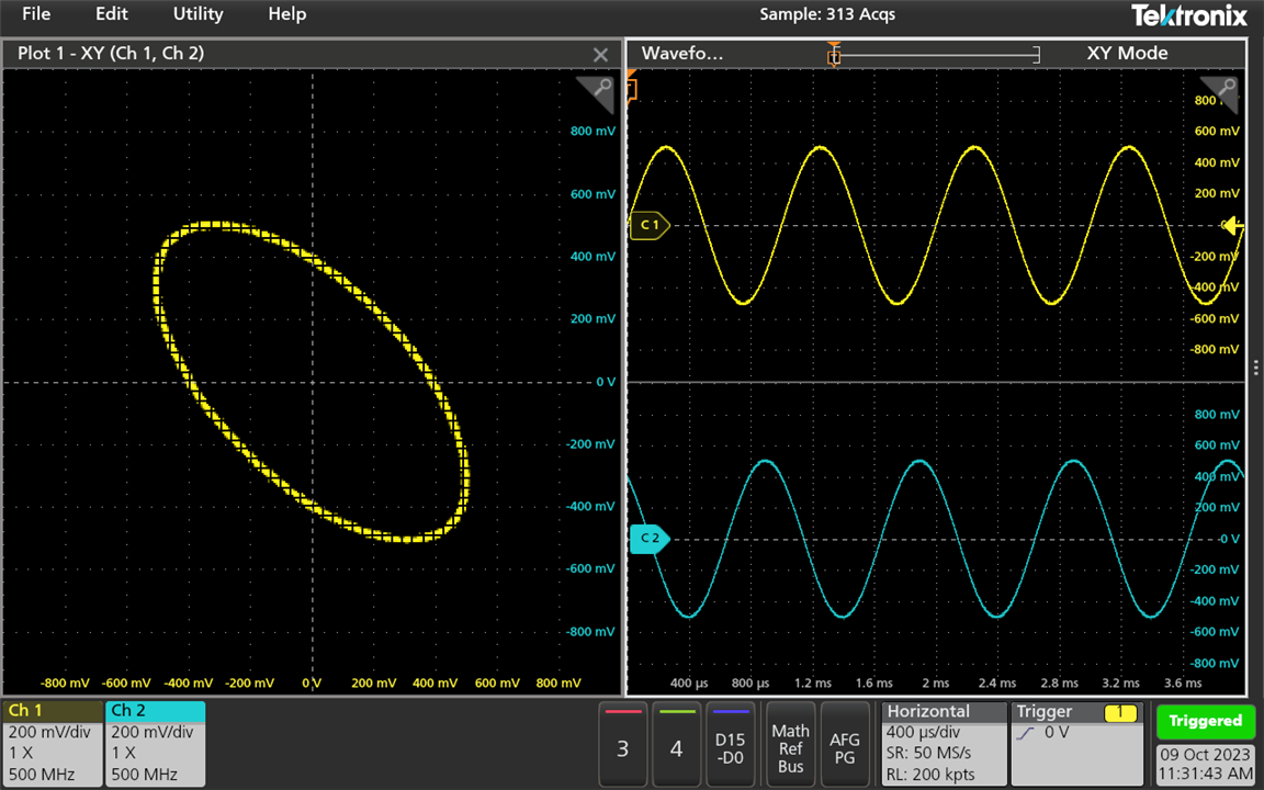
There is also the possibility to perform X-Y display using two channels.
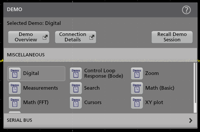
The MSO24 also has onboard demonstration pre-sets which can be recalled, some of which is designed for use with hardware.

Finally, there is a license options catalog, for those who want to browse the options available for their 2-series MSO.
Overall, it seems most of the important functionality is there, considering the market position of the oscilloscope as the entry-level into mainstream oscilloscopes. However, I can’t shake the feeling that the 10Mpt memory, while not entirely generous, could be much better utilised if it could be segmented. Without this feature, I’ve been left hoping that the oscilloscope would trigger (and stop) on a very specific event. Segmented acquisition would allow for splitting the memory into shorter records to allow for multiple acquisitions that can be replayed to find the event of interest. Ever since I had access to this functionality on the RTM3004, I’ve taken its existence for granted!
Responsiveness & Stability
The MSO24 takes around 1 minute and 16 seconds to start up and 28 seconds to shut down. This is not particularly speedy, but this may also do with the configuration that has 1 TekDrive and 1 network share mounted.
On the whole, in ordinary use, the MSO24 feels responsive enough. The knobs certainly don’t feel as responsive as analog or even some of the better “fixed function” DSOs, but they do feel more snappy than the Rohde & Schwarz RTM3004 I previously reviewed making it fairly comfortable to use.
The speed of waveform updates and measurements, however, did seem a bit below-par to me. The default record-length settings seem to limit memory usage to a fraction of the 10Mpts capability. If manually selecting record length to 10Mpts, the acquisition is visibly slowed down and with certain features (e.g. FFT), it can slow down to the point that the cursor changes into a watch and the unit is very slow to respond to touch input. I suspect this is down to the processing power of the SoC used.
The firmware appears to be quite stable – there were no major issues that caused reboots nor were there bugs that affected readings or performance that were noticed during the review. The only anomaly was this message after changing font size, loading default setup and rebooting:
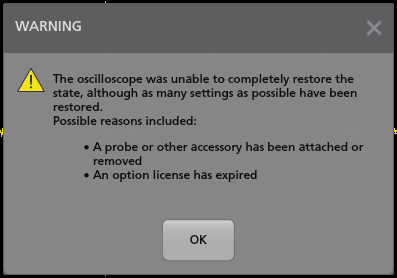
This may be related to a previous issue that resulted in the font size not being memorised through a reboot previously. This was easily remedied manually.
Acoustic Noise
While small and seemingly lacking in large fan grilles, the Tektronix 2-series MSO actually hides a fan inside.
It seems to be arranged such that heat is exhausted through vents in the top-rear portion of the unit. While starting up, the unit runs its fan at full-blast, which sounds a bit like an air-conditioner running on high – mostly wind-noise with very little in the way of a whine.
Once the unit has booted, the fan is thermostatically controlled and settles down into a quieter regime. The sound is more like a low-whisper at room temperature, with only the slightest intermittent coil buzz audible. Compared to most larger bench-top units, this one would be quieter.
Form-Factor & Mounting Options
The Tektronix 2-series MSO likes to call itself a “tablet” form oscilloscope, although I would consider it more of a portable oscilloscope. Its thickness and arrangement of ports makes it somewhat unwieldy to handle single-handedly, and its weight with battery approximates a laptop computer.
While it is provided with a desk stand for bench-top use, one of the claims-to-fame is the presence of a VESA mount to allow the oscilloscope to “give back” some bench space. To test this, I purchased a third-party gas-spring monitor arm intended for medium-size monitors.
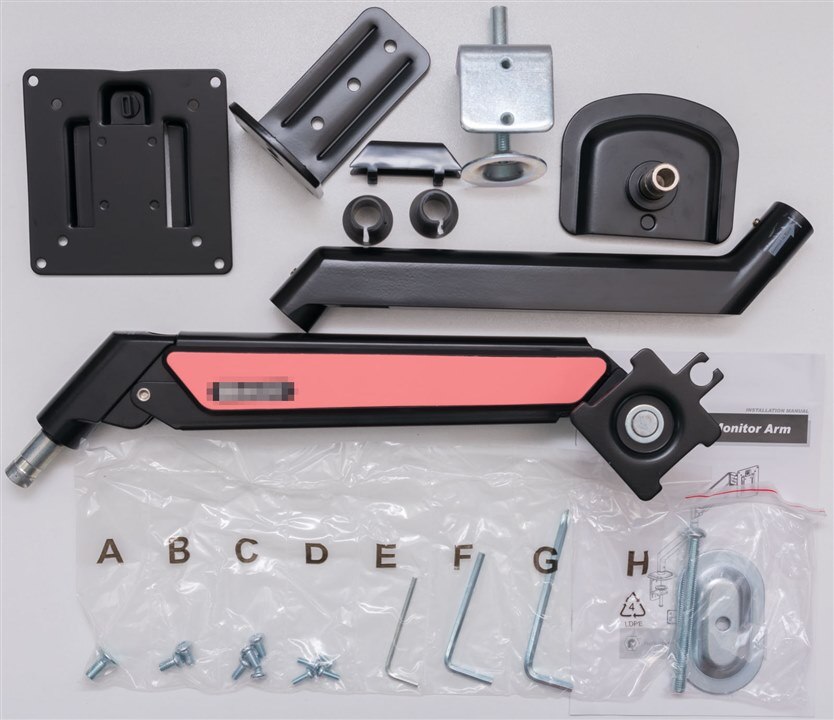
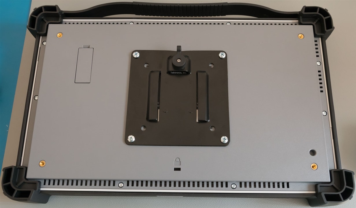
It was successfully assembled and installed onto my secondary bench. It comes with a “quick release” VESA mount plate for ease of mounting the monitor (or oscilloscope).
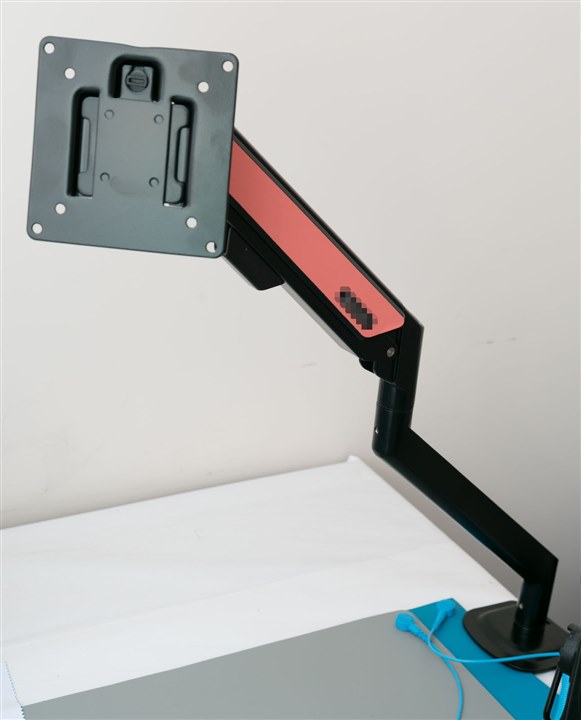
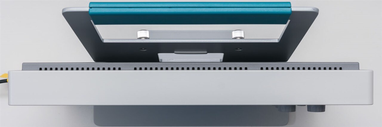
This is screwed to the back of the MSO24 and the unit is then mated with the arm.
A functional configuration would look like this:
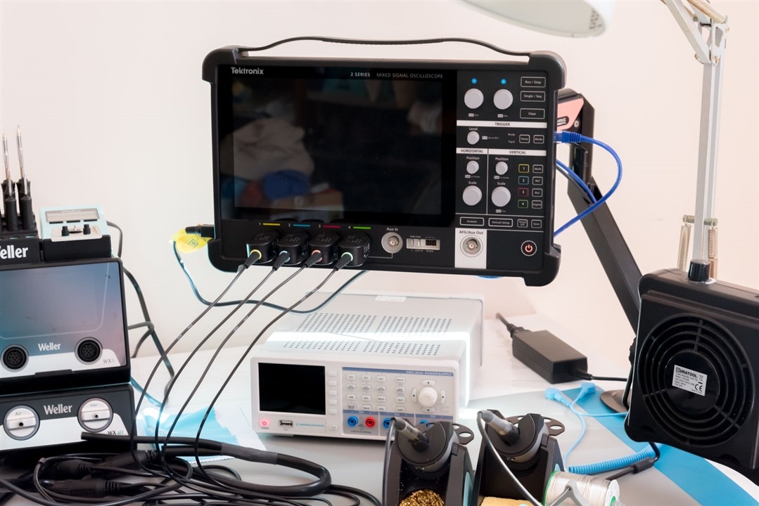
The cable of the DC-side of the power adapter for the unit is only just long enough to go through the arm in a cable-managed way. A longer lead would provide more flexibility in placement of the AC adapter. However, aside from this, the arm was able to hold the oscilloscope in various positions, off the bench, with all probes and cables connected.
After using this configuration for a few days, I found that I liked the fact that elevating the oscilloscope off the bench provides for more bench space. It also provides the ability to have the oscilloscope screen more at eye-level, making for better ergonomics and no sore necks. Interacting with the buttons does take a little more care, but is still easily achieved. When it is not needed, it can be simply pushed out of the way. The light-weight of the MSO24 makes such a monitor arm configuration realistic.
I suppose the main downside is the power and data ports that stick out of the side of the unit. These result in cables jutting out of the side of the unit, which means that users need to take some care to avoid “karate-chopping” a plug and putting stress on the connectors of the oscilloscope.
Another would be the fact that the mounting options are all very reliant on the VESA mounting holes on the 2-series MSO which seem to be brass threaded inserts in a plastic casing. The top two holes, especially, are relied upon for the desk stand (when at an angle) and the portable kick-stand. Because VESA mounts are not intended for frequent swapping, conversion between a desk-dwelling configuration to a portable mobile-configuration and back takes a bit of effort and risks potentially stressing these mounting holes. Another potential stress on the mounting holes would be the use of the 2-series MSO with third-party monitor mount arms that have very tight pivot joints, where users would be exerting force through the oscilloscope to pivot the arm into a desired position. I’m not sure whether this may result in long-term durability issues.
Documentation & On-Board Help
As part of this part of the review, I went through the Datasheet, Quick Start, Help and Specification and Performance Verification Manuals on Tektronix’s website. I found the quality of the documentation to be very good, practical and very accurate. It was definitely helpful to read and not excessive in length.
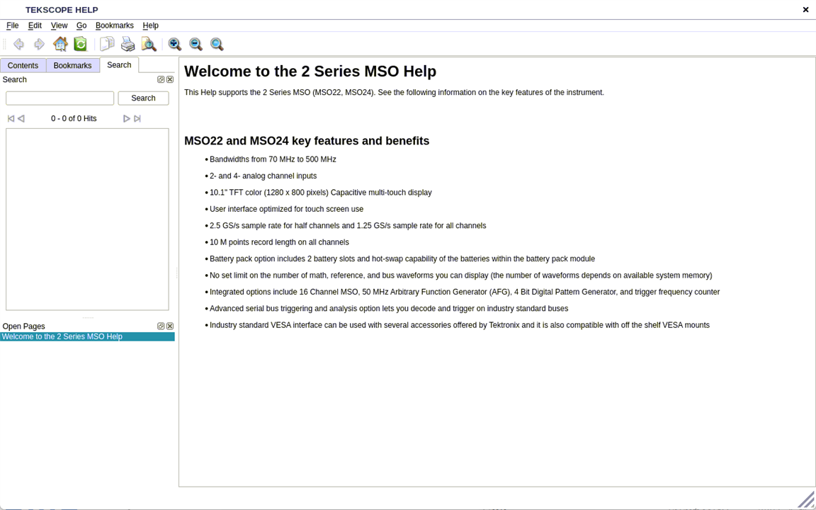
There is an onboard help on the MSO24 which can often be accessed by pressing on a “?” icon in the top right of a window. This is nice as it brings you to the relevant chapter of the help manual, however, the browser itself is not touch-optimised. As a result, scrolling must be achieved with the scroll-bar and the search boxes do not work as tapping in them does not bring up the on-screen keyboard. Use via VNC remote control or with a keyboard and mouse is possible, however, but this should be improved.
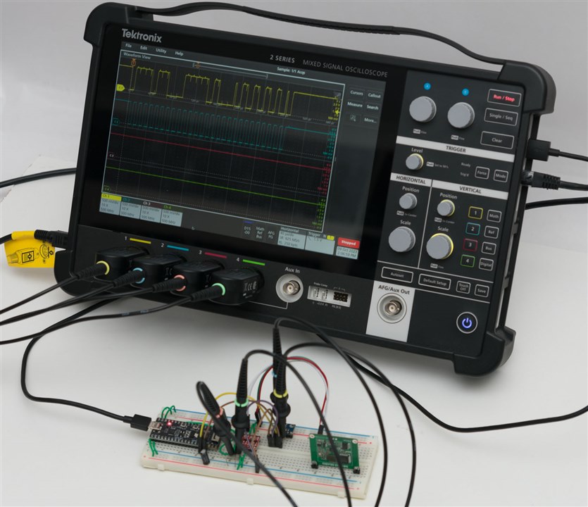
Practical Demonstrations
This section will focus on a few practical demonstrations of the capability of the MSO24.
FRA/Bode Plot
The MSO24 can produce a bode plot on its own using its internal AFG (or supported external AFG) and two of its oscilloscope channels. This requires the 2-SOURCE option to function.

The analysis allows the input and output channels to be set, a choice of AFG, impedance setting, points per decade, start/stop frequencies and amplitude profile. Once the settings are configured, the Preset button is pushed, followed by the Run/Stop button on the oscilloscope to initiate the measurement sequence.
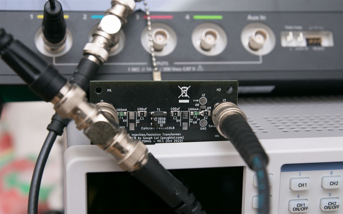
I decided to test the feature on a PCB I designed as a test carrier for a Coilcraft PWB1010LB wideband RF transformer.

The resulting bode plot shows that the transformer has a relatively flat pass-band.

If I move the waveform view out of the way so that it “floats”, we can get a better view of the bode plot with zoom. It shows the -3dB points stretch from about 350Hz to 15MHz.

I did encounter issues where I had selected many (>50) points per decade and the scan was taking a while. It seems the script runs into a “Runtime Error” and stops mid-test. Reducing the number of points allows the test to succeed.
Serial Decoding
Serial protocol decoding is available with the 2-SERIAL option. As it just so happens, I’ve got a little project going on that is using both I2C and UART communications.
This would be a good test of the ability to decode serial buses.
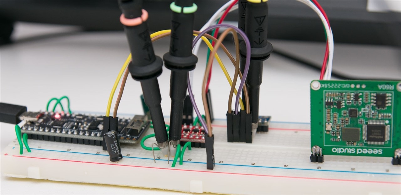
For added realism, I’ve decided to probe nicely and use the spring grounds for this. This ensures we get a quality waveform without the influence of a long ground loop.
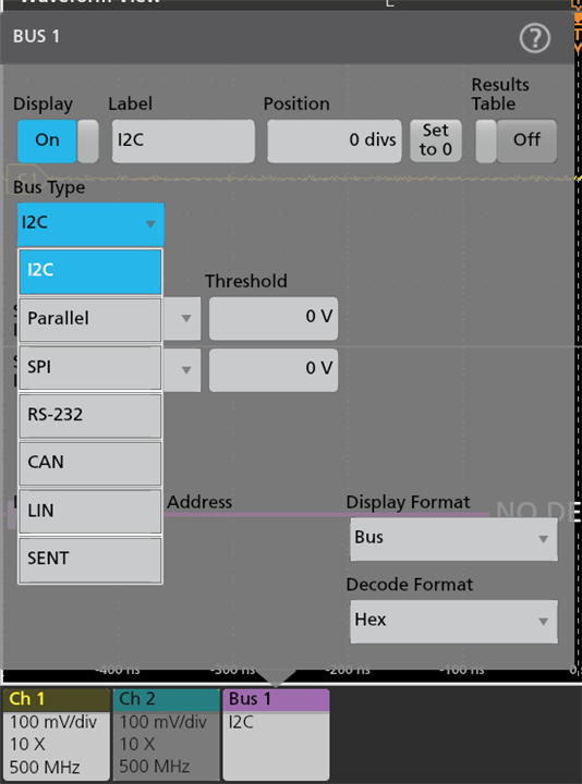
Serial decoding can be accessed through the badge for Bus. The MSO24 supports I2C, Parallel, SPI, RS-232, CAN, LIN and SENT only at this time.
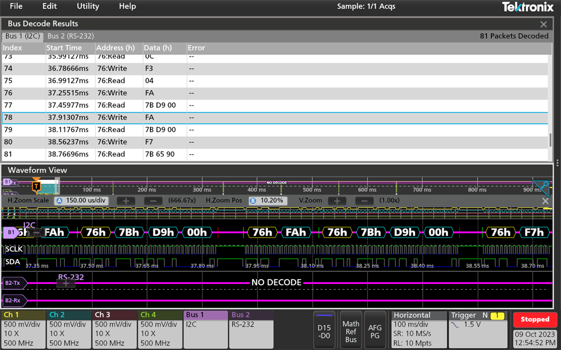

Bus decoding operated as expected and the data can also be exported from the bus table to .csv. The font for the bus trace is a bit big, meaning that it isn’t possible to see much when zoomed out unfortunately.
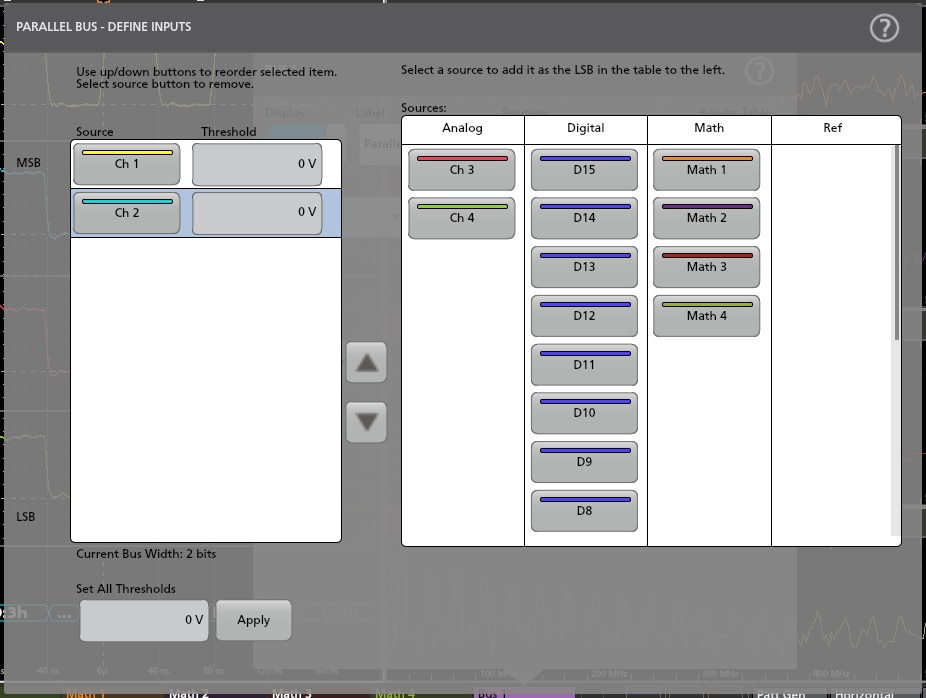
The parallel bus decoding feature is interesting, as it seems to be able to use a mixture of digital and analog channels – something that not all models of oscilloscopes can do.
External Triggering
The presence of an external trigger input allows for the oscilloscope to free up its analog channels for something useful. As a demonstration of this, I’ve captured VGA with the MSO24, using the external trigger for the vertical synchronisation pulse.

Red, green, blue waveforms and horizontal synchronisation pulses are being captured by the four channels.
Arbitrary Frequency Generator/Pattern Generator
The Arbitrary Frequency Generator (AFG) and 4-bit Pattern Generator (PG) are enabled with the 2-SOURCE license. The AFG supports up to 50MHz (sine) or 25MHz (AWG) output, while the PG supports 25MHz.


A number of parameters can be set, but of note is that the generator can only reach 5Vpp in High-Z and half of that in 50-ohm mode. This makes it less powerful than some dedicated AFGs.
For example, here is a cardiac waveform …

… and here is a cardiac waveform, with 50% noise added.

The AFG doesn’t seem to support modulation, but it does support arbitrary waveform generation by uploading a .wfm or .csv file of up to 128kpts.

To stress it out, I decided to call for a 25MHz square wave, connecting directly with a piece of coax and the output was decidedly rounded. The measured rise time was around 7.38ns and the fall fine was 7.64ns.

The pattern generator can be configured for 2.5V, 3.3V or 5V output, with either high, low, high-impedance or toggle output at a configurable bit-rate. A 4096-long sequence can be uploaded as a .csv as well.
Using some jumper wires and carefully connecting the probes with spring ground, we can observe the output of the pattern generator.

The pattern generator was successfully toggling cleanly across all four channels at the maximum of 25Mbit/s. This was cleaner than I expected given the wiring, although having the pattern generator output on ordinary 2.54mm pins on the front panel seems less than ideal as they can be a little fragile (e.g. when students bend pins, for example).
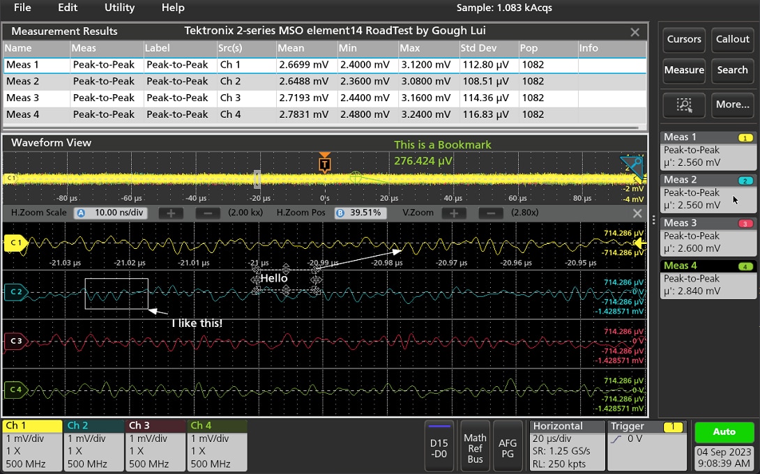
Annotations
While not a serious example, I did try out the annotation features and was surprised by the variety of elements available. There was some difficulty in getting the arrows to point to the location I wanted, but it’s still pretty good for marking up signals of interest.
Ethernet Signals
I decided it was also good to try scoping some ordinary signals in an “analog” sense.

At first, I tried this old 10Mbit/s Ethernet device – that signal doesn’t look all that healthy but that may just be because the device is a bit “hacky”.

I then stepped up to 100Mbit/s Fast Ethernet, where the MLT-3 encoding is clearly seen. Persistence is used to form a quasi-eye-diagram while cursors are used to measure the bit-clock.
FFT Analysis
I also tested the FFT capabilities with the probe connected to some wire.

It had no trouble seeing local AM radio stations, ABC RadioNational 576kHz, ABC NewsRadio 630kHz and ABC Radio Sydney (2BL) 702kHz.
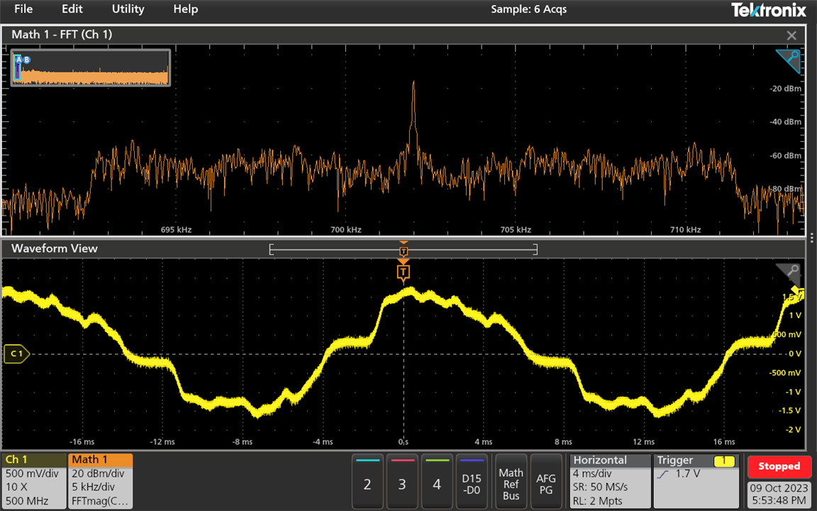
We can also see some of the AM modulation when zooming right in. As this is FFT rather than a proper spectrum analyser, the analysis width and resolution are related to the time-base/record length.

It is also possible to resolve FM radio stations as well.
Conclusion
The Tektronix 2-series MSO is supported by excellent documentation which made the getting started process much easier. The process involved a firmware update to V2.2.6.1052, running self-test and signal path compensation (SPC), setting time zone and adjusting probe compensation trimmers. In the process of examining the firmware, I learned that the unit is codenamed “Lexington” and is based around a ZynqMP SoC running PetaLinux with a root user. The unit has a Goodix capacitive touch screen controller and a number of chips including si570, si5324, pca953x, tps65086, ina2xx, tps65086, at24/25, jesd204b, bq32k and max310x. Software-wise, it has Python 2.7 and 3.7, pyvisa and x11vnc. The main application is called “scopeapp”.
As the MSO24 had the 2-DDU option unlocking all features, I was able to access features which would normally require 2-MSO, 2-SOURCE, 2-SERIAL or 2-ULTIMATE to access, but on a time-limited basis. However, as I wasn’t supplied the digital probes, this review does not consider the digital channels.
I found the 10.1” touch-screen to have good resolution and sufficient brightness and contrast for indoor usage. Outdoor usage may prove difficult. The glossy finish of the touch-screen digitiser does cause significant amounts of glare, even when used indoors. The unit’s probe interfaces are plain BNCs without an additional grounding ring which the P6139B could benefit from. This means that the MSO24 isn’t suited for use with TekVPI or FlexChannel probes.
The buttons and knobs on the front panel are well organised and work as expected, although the membrane technology means shorter travel and less tactile definition. It also makes me hesitant about its long-term durability. Although it may be easier to wipe down, it must be remembered that there is no ingress protection rating as there are gaps underneath each knob.
While the unit was reviewed without the battery option, another key point is that the use of a grounding cable is required whenever any voltage higher-than low voltage is being probed and the unit is operating from battery for operator safety. When operating from mains, it is grounded through the power supply.
The software user interface looks neat at first glance but hides a lot of functionality behind its very grey colour scheme. Functions can be accessed through a mixture of toolbar menus, badges, nested-badges, quick menus, flip menus and right-click pop-up menus. Some features require multiple taps to access. This requires some getting used to, as features may not always be easy to find at first glance, although users will learn over time where certain features reside. Touch targets are generally well-sized for ease of operation, although I do find that the smaller font size is advantageous to maximising the use of the limited screen real-estate.
The oscilloscope has all of the functions one would expect from a unit of this class – the ability to save and export waveforms, settings, sessions, reports and screenshots; the ability to perform math functions, FFT, searches, masks, measurements, cursors and X-Y display modes; the ability to run demos, look at license information, retrieve help documentation and perform secure erasure of data. Perhaps the only thing I really miss is segmented memory – a feature normally found in oscilloscopes in the tier above which makes capturing the “occasional” event significantly easier. It was found that the onboard help browser doesn’t operate well with touch interactions.
The unit itself takes about 1 minute and 16 seconds to start-up and 28 seconds to shut down which is not particularly speedy. In use, the knobs are sufficiently responsive, but not quite analog-responsive, as there is some noticeable but not annoying level of delay. The speed of waveform updates and measurements in automatic mode is acceptable as it seems to limit record lengths, but when longer record lengths up to 10Mpts is used, it is possible to slow down the unit to the point that it starts becoming very slow to respond to touch input. Overall, firmware stability was good without any major show-stopping issues.
The unit is relatively quiet. While booting, with the fan at full speed, it sounds like an air conditioner running on high with mostly wind noise and no whine. When the unit has booted, the fan settles down into a slower speed which is like a low-whisper, with only the slightest intermittent coil buzz. It is quieter than most benchtop units.
The unit’s versatility in VESA mounting is demonstrated and allows for a practical way to free up bench space by mounting the unit on a third-party monitor arm. This also improves ergonomics by having the screen at eye-level, although care is needed to avoid “karate-chopping” the cables that enter from the side of the unit. A longer DC-cable would also improve positioning flexibility. I do have some concerns about the durability of the threaded brass inserts in the MSO24’s body, as so much of its kit relies on the VESA mounting holes to function. Pivoting the oscilloscope on the monitor arm will transmit those forces through the oscilloscope’s casing, causing stress. It is also noted that conversion between bench-dwelling and portable mobile modes of operation will necessitate changing VESA mounts which may add further stress.
A practical demonstration of the oscilloscope’s bench capabilities included the construction of a bode plot for a wide-band RF transformer on a PCB of my own design, decoding of serial buses on an embedded systems prototype, capturing of VGA signals using external trigger, testing of the arbitrary function generator and pattern generators, drawing on-screen annotations, collecting Ethernet signals and performing FFT analysis to detect AM/FM radio stations.
---
This blog is a part of the Tektronix 2-series MSO RoadTest Review.