


I’m sure some readers will be interested to know what is inside the Weller WXsmart kit. While I didn’t propose to do this in my application, I decided to be a bit adventurous and do some non-destructive teardowns for your enjoyment. I hope you enjoy this bonus post!
Table of Contents
Teardowns
No devices were harmed in the process of teardowns, however, I did not opt to take apart any of the handpieces because they didn’t seem to be easy to get apart without potentially fatally damaging them.
WXsmart
Removing a few screws allowed the top cover to come right off, revealing the insides.
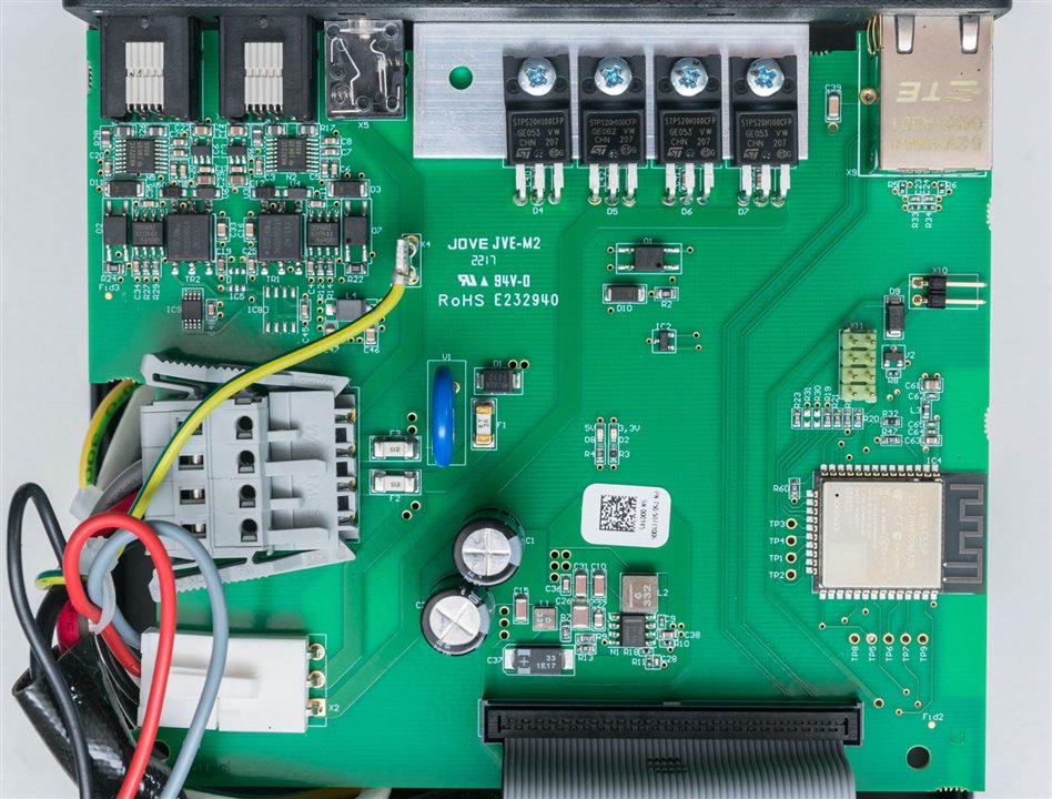
The thing we are greeted with is a rather large PCB, but with very few components. The AC from the toroidal transformer enters in on the mid-left and goes out to the front-PCB on the bottom left. The input is fused and surge-protected. The Ethernet jack is on the board in the top right, but it seems to be wired through to the ribbon cable that links this board to the front-PCB.
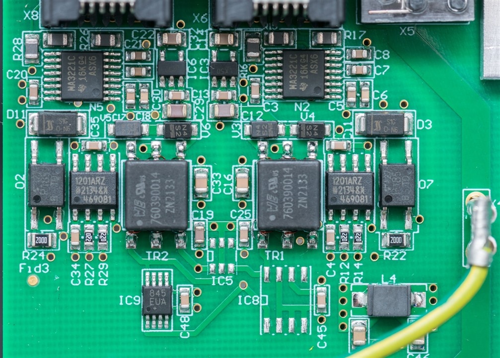
The top-left corner of the PCB is dedicated to serial communications, which appear to be transformer isolated and optically switched in some way.
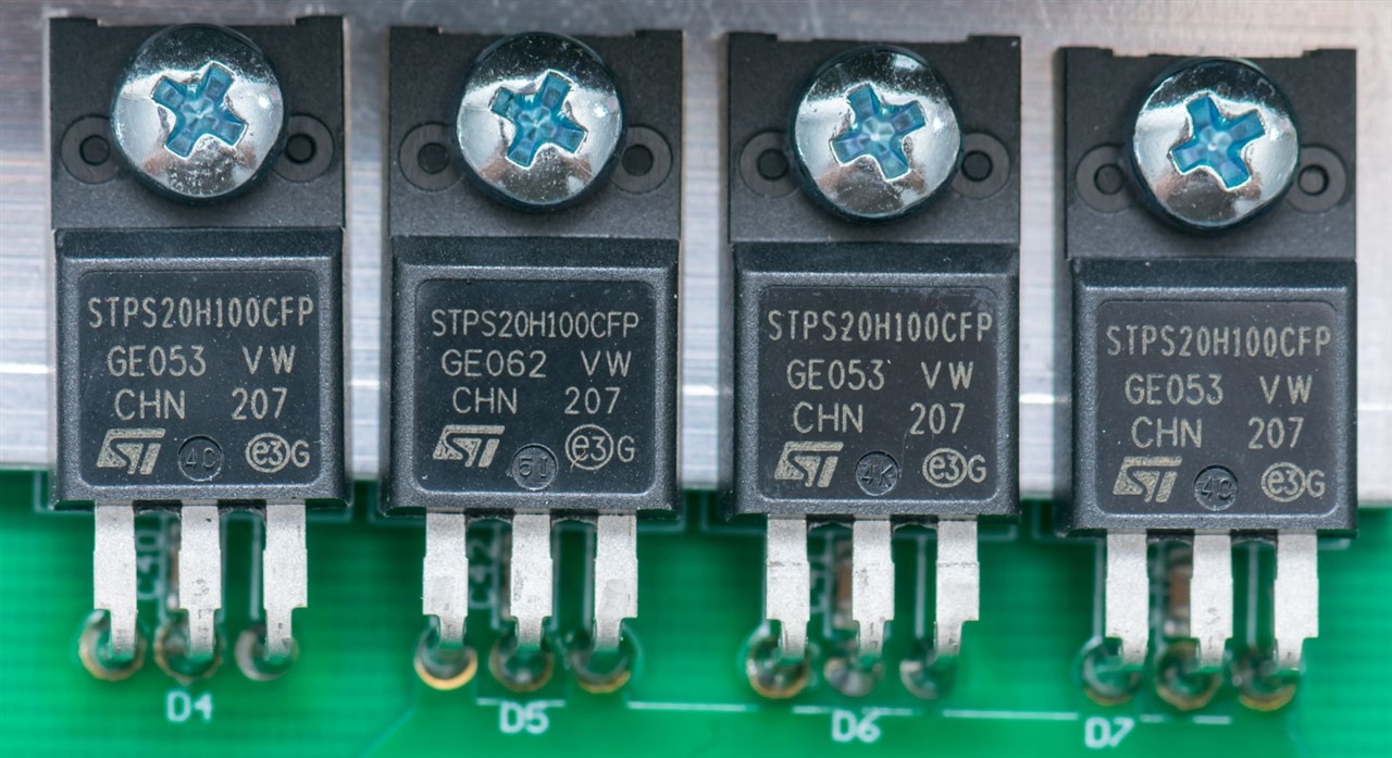
The middle-top portion of the board is where the “heat” is generated and conveyed to the heatsink. A row of four STMicroelectronics STPS20H100CFP 2x10A 100V Schottky rectifiers seemingly from two or more different batches (D5 is noticeably different in coding, D6 has a different moulding mark) may be providing rectification of AC to DC.
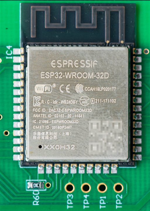
No, you’re not imagining things – there is an Espressif Systems ESP32-WROOM-32D in here. I’ve built a few things using this particular module, so it’s a familiar sight to me and it’s here providing the Wi-Fi connectivity with its onboard antenna.
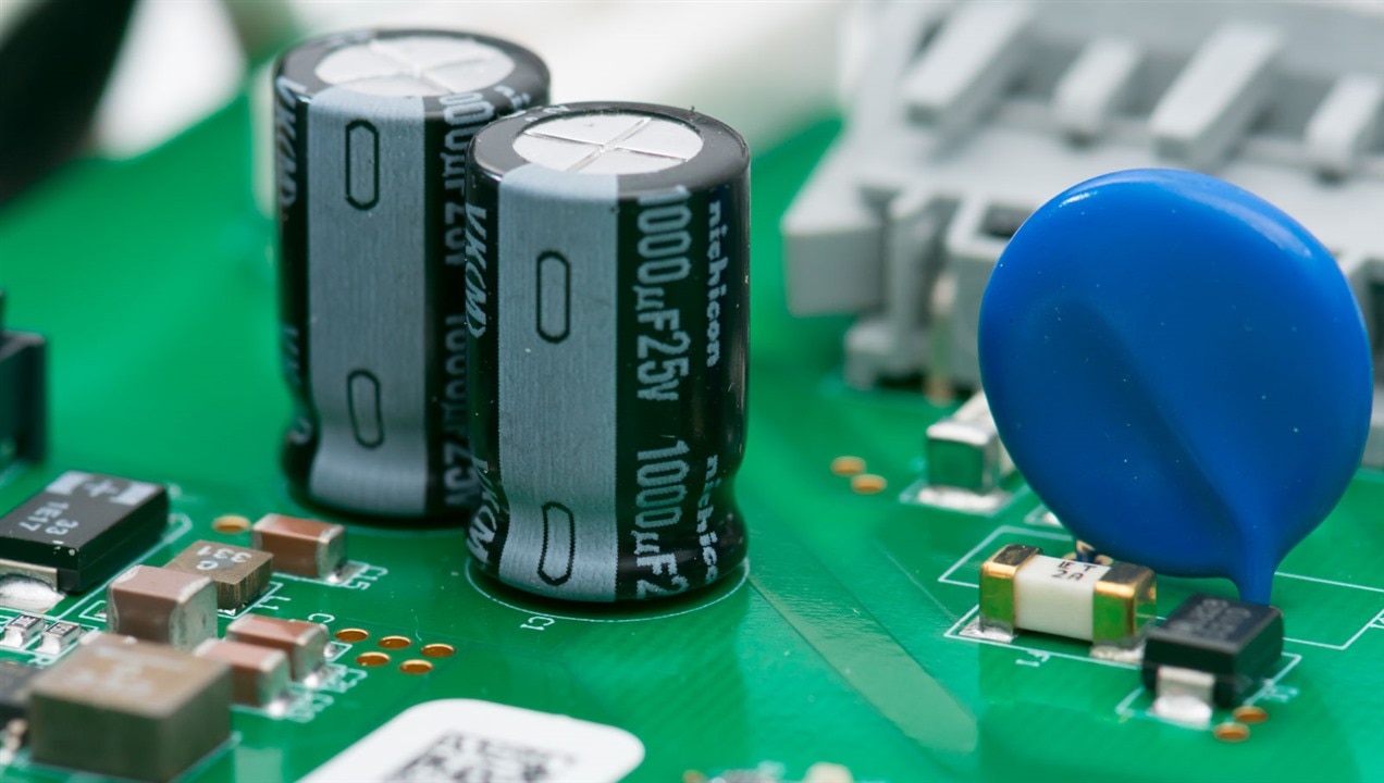
There are electrolytic capacitors on the board and while they are Nichicon products, they opted for the VK-series which is 85°C rated which is perhaps not as premium as the 105°C capacitors that are relatively commonplace nowadays. Then again, as they are smoothing mains-frequency ripple, perhaps this is not as demanding as switch-mode applications.
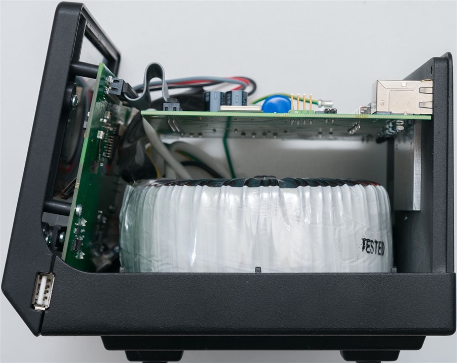
A view from the side shows how the top PCB seems to be supported primarily by the heatsink attachment to the insulated TO-220 packages. This arrangement may be prone to sensitivity to vibration and shock in transit – it would be nice to see more support. The bottom-half of the unit appears to be dominated by the toroidal transformer.
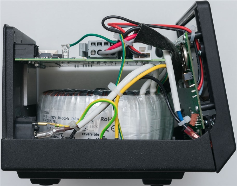
A view from the other shows how some of it is wired together. It is a tight fit inside for the front-PCB and that brown programming header sticks out precariously at an angle to the board.
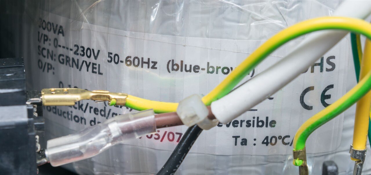
As expected, the transformer is appropriately rated at 300VA, this being 230V rated. The 120V version of the WXsmart is likely to have a different toroid.
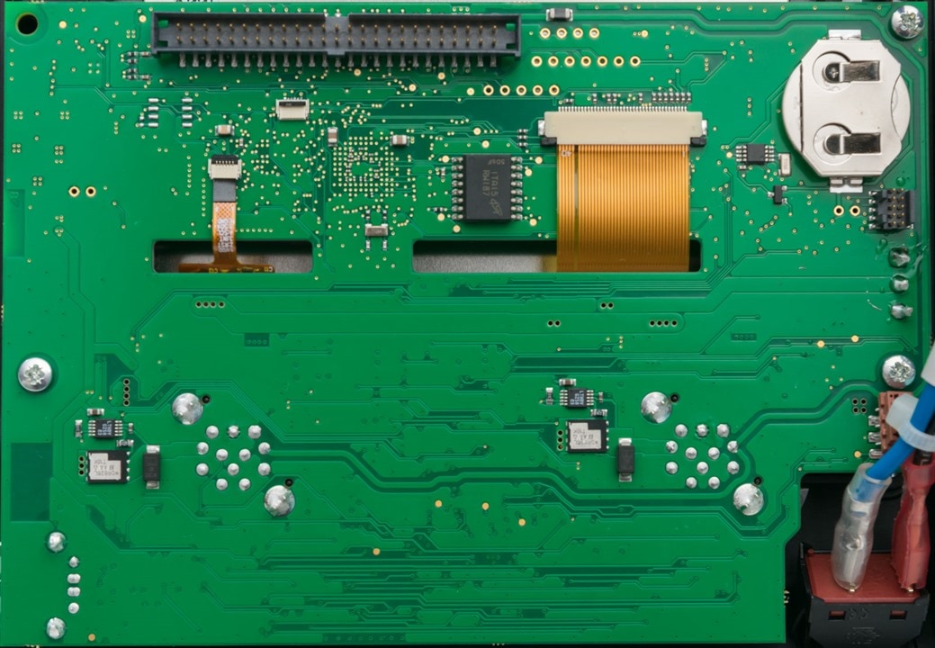
The front-board is perhaps where most of the smarts reside. On the back, a VARTA coin cell (likely CR2032) is visible for RTC backup. This is perhaps most important for security as TLS certificate revocation and expiry requires accurate time. Ribbons for the LCD and touch panel go through slots in the board. The backs of the output channel connectors can be seen along with what appears to be a MOSFET, driver and protection diode. There is a Micron MT25QL512ABB8ESF-0SIT 512Mbit serial flash which may be containing the firmware.

The front of the board is much more interesting – the part in white in the top-left may well be a beeper for audio feedback. The main show seems to be orchestrated by a STMicroelectronics STM32F746 216MHz ARM Cortex-M7 with 1Mbyte of flash. Next to it is a Micron MT48LC4M32B2B5-6A 128Mbit 133MHz SDRAM chip. Nearby appears to be an ATMEL flash and SMSC (USB?/Ethernet?) transceiver.
Looking further down the board, it seems the channels are handled by a PIC32MX460F 80MHz MIPS core. The shunt resistors for power measurement are visible, with a number of FETs (Vishay SiDR626LEP), drivers (Analog Devices LTC7004), TVS protection diodes (LittelFuse ?), RGB LEDs and opamps (LM339). A PA9545A I2C switch is also seen on the board with a TI TLC59116 presumably doing LED driving duties.
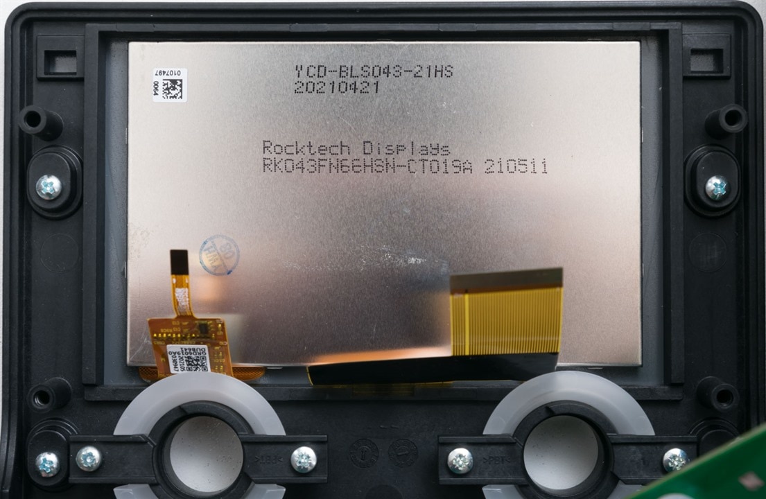
Finally, the front of the unit has a display from Rocktech Displays, marked RK043F55HSN-CT019A dated 22nd May 2021. Above this, it is marked YCD-BLS043-21HS, dated 21st April 2021.
WXair
Disassembling the WXair also took only a few screws to remove the top cover.
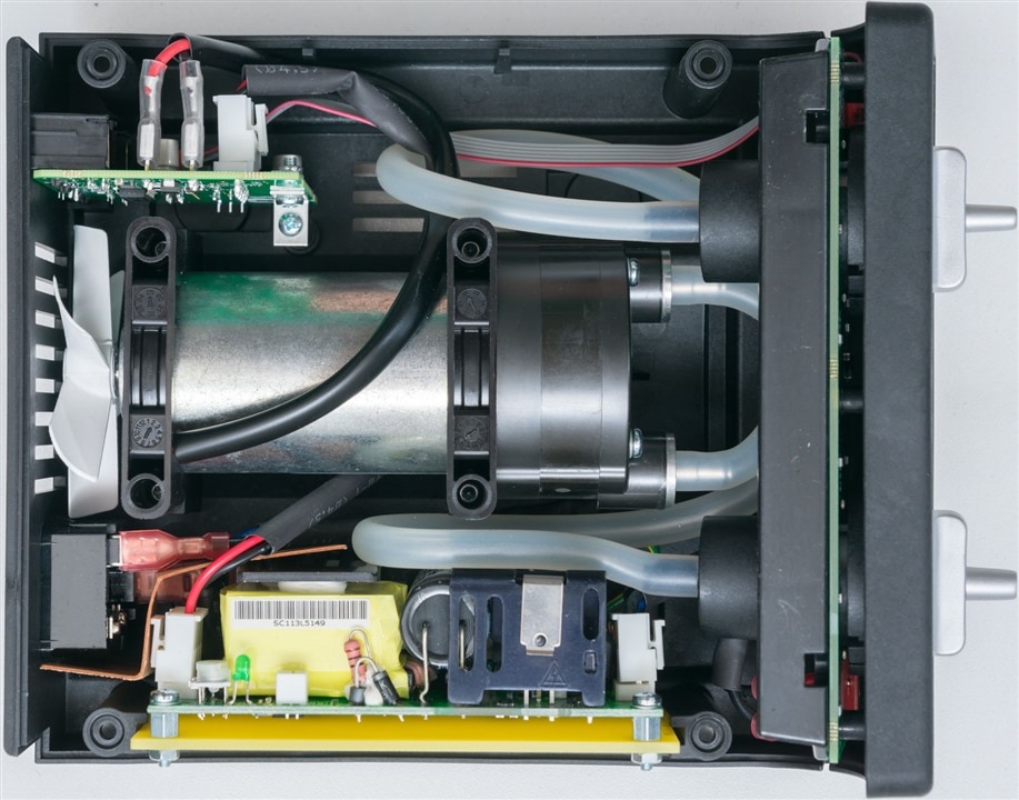
The inside of the unit is relatively packed and a piece of insulator card can be seen between the power input and the switch-mode power supply.
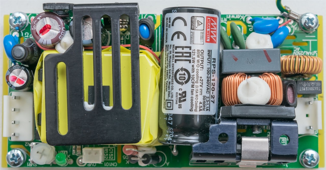
Disassembling the unit reveals a Meanwell RPS-120-27 power supply with an output of 27V at 4.5A rated at 85W without cooling and 121.5W with 10CFM fan cooling. This part is Made in China and looks to be a reasonably good design.
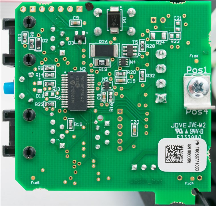
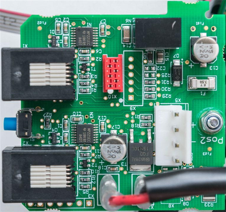
The PCB in the rear corner seems to be responsible for communications and perhaps a bit more. It is based around a PIC18F25K42 16MHz 8-bit microcontroller. On the reverse side, Texas Instruments MAX3221E chips take care of the RS-232 levels. Other than this, there is a relay present, an onsemi FQD19N10L 100V 0.1mOhm N-channel MOSFET (likely for controlling pump speed) and a 3.5A fuse amongst other more general components.
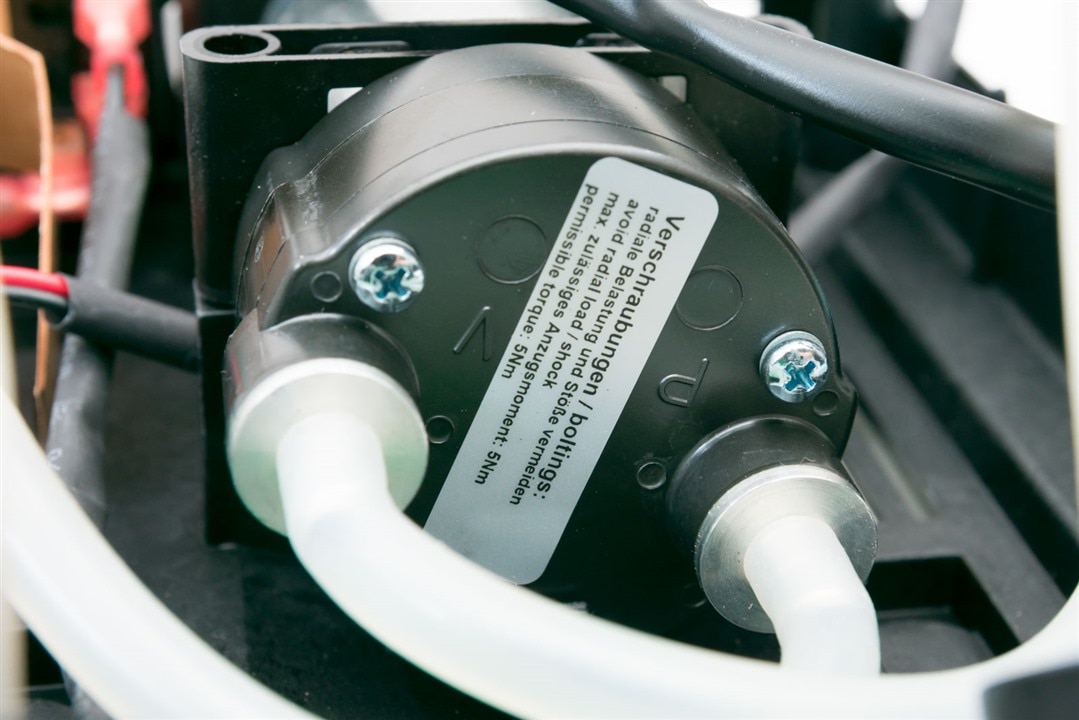
I didn’t identify much about the pump itself, but it seems to be pulling a vacuum from one side and pumping to the other, which also explains why it’s probably not a good idea to have a tool attached to both ports at the same time.
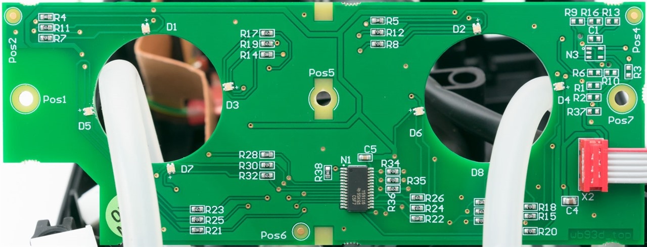
The front PCB on this unit is very simply just a place for LEDs, their driver IC, and not much else.
WCU
Taking out the screws on the back allowed me to get into the WCU with ease.
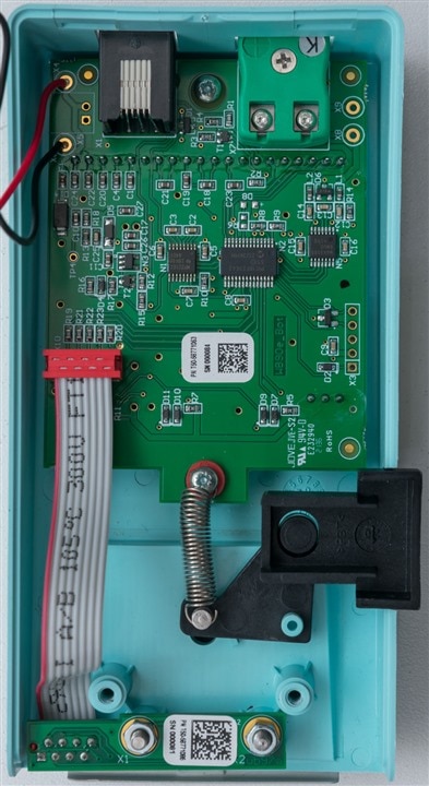
Internally, a main-board rests at the top with a ribbon connecting a daughter-board containing the active contacts for the thermocouple. The other “contact” is not live, merely providing spring force to hold the thermocross taut.
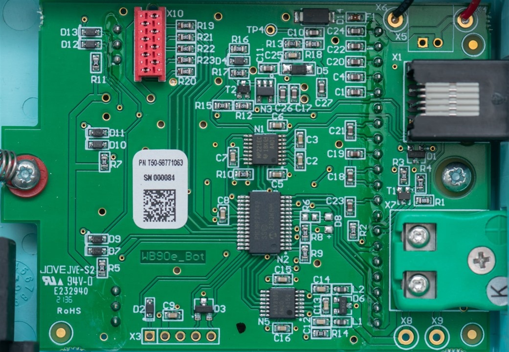
A closer look at the PCB shows that this board is labelled WB90e and is based around a PIC18F27K42 with serial interface handled by a Texas instruments MAX3221E as well. Measurements seem to be handled by an Analog Devices MAX31856 Precision Thermocouple to Digital Converter.
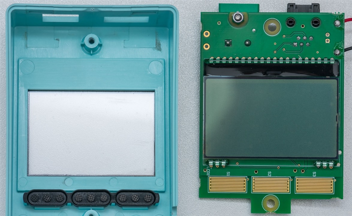
The front side consists of the monochrome matrix LCD glass and contacts for the rubberised push-buttons.
Testing the WCU Serial Connection
I was curious – what is on the 6p6c roll-over leads? I know it’s serial and we are told it is 1200bps, but what is the pin-out and what are the signalling voltages involved? To investigate, I crimped my own 6p6c lead breakouts to do some measurements and came to this conclusion:
1 N/C?
2 GND
3 WXsmart TX
4 WXsmart RX (+/-6V, Idle Low, 1200bps)
5 GND
6 DSR? (3V if WCU On)
It seems that the roll-over of the lead is used to swap the RX and TX, so grounds have to be symmetrical. The outermost contacts seem to be unused on one end and indicate the power status of the WCU on the other. Perhaps a roll-over 6p4c cable would have been enough and I might not actually have needed to crimp my own 6p6c (as the official cable seems to be out-of-stock everywhere). But use the information above at your own risk!
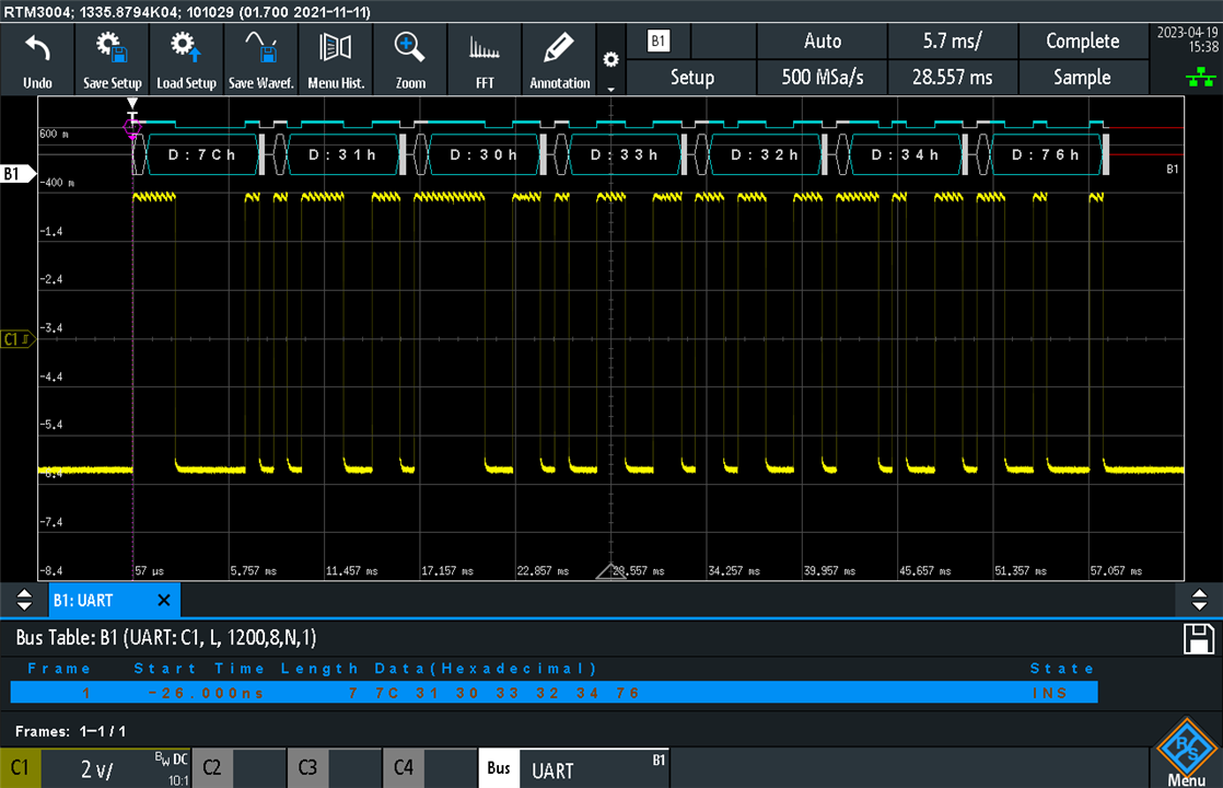
Using the RTM3004 confirms the use of 1200bps idle-low serial with a voltage swinging between about ±6V.
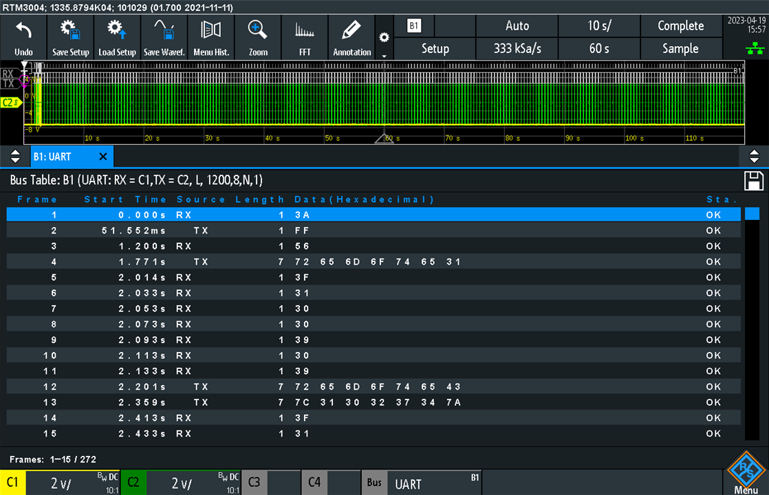
Decoding a longer time-period shows a two-way communication protocol – this was attempting to run a calibration with no tool connected (if I recall correctly). I believe documentation about some of the protocol and pin-outs may be available from Weller.
Retail Replacements
As I mentioned in the earlier chapter of usage scenarios, I experienced a failure of one of the tips and intermittent behaviour with another. I returned the tips to Weller for investigation, however, they were gracious enough to replace the tips and also supply a handpiece as I wasn’t sure if an intermittent contact inside the handpiece was to blame. As a result, we get to experience what it would be like to unbox a retail handpiece.

The handpiece comes in a thin white cardboard box with Weller-blue accents.

A label on the back indicates the handpiece included inside.

A thick multilingual book of information is folded inside the box with the handpiece packaged inside a zip-lock plastic bag.
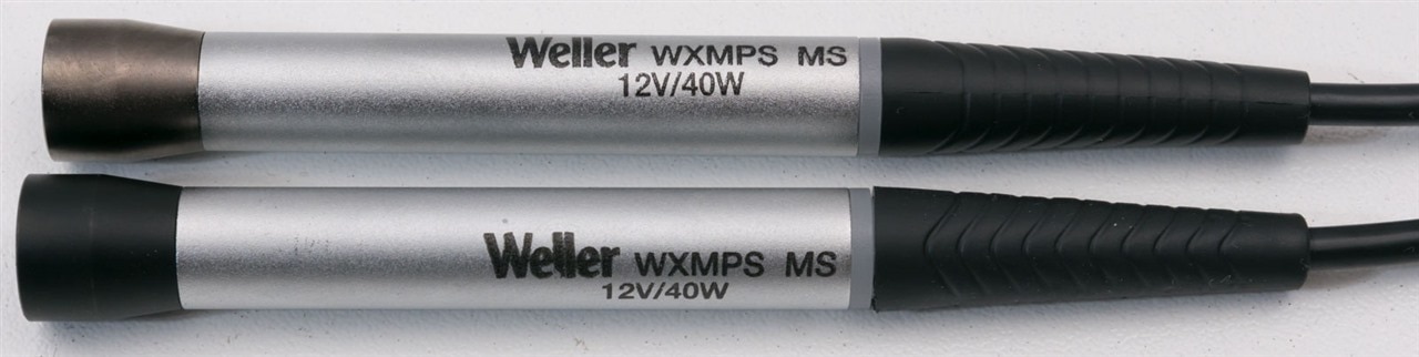
Comparing the replacement WXMPS MS with the original, the new one has a lighter grey-coloured collar near the tip, rather than a black-coloured collar. Aside from that, they seem to be identical. As they are well constructed, I decided not to try tearing down the old one just yet.
Conclusion
While not originally proposed for the RoadTest, I did complete a teardown of much of the kit without harming it. In the process, it revealed a lot about the components and design within the units, but also raises interesting questions as well.
The WXsmart unit itself uses a large toroidal transformer which is wound for a single input voltage at its core, but this is controlled with a PCB containing four STMicroelectronics STPS20H100CFP 2x10A 100V Schottky rectifiers attached to a bracket which also supports the weight of the PCB. The serial interfaces appear to be transformer isolated and optically switched somehow. The Wi-Fi connectivity comes courtesy of an Espressif Systems ESP32-WROOM-32D and there are a pair of wet electrolytic capacitors from Nichicon’s VK-series which are 85°C rated (rather than 105°C for longevity). Other key parts include a VARTA coin cell for real-time-clock backup, a Micron MT25QL512ABB8ESF-0SIT 512Mbit serial flash which may contain firmware, a STMicroelectronics STM32F746 216MHz ARM Cortex-M7 with 1Mbyte of flash, a Micron MT48LC4M32B2B5-6A 128Mbit 133MHz SDRAM, a PIC32MX460F 80MHz MIPS core, shunt resistors for power measurement, Vishay SiDR626LEP MOSFETs, Analog Devices LTC7004 drivers, TVS protection diode, RGB LEDs, LM339 opamps, a PA9545A I2C switch and a Texas Instruments TLC59116 LED driver. The display appears to come from Rocktech Displays, marked RK043F55HSN-CT019A and YCD-BLS043-21HS.
The WXair unit is built around a pump powered by a Meanwell RPS-120-27 power supply rated at 27V at 4.5A and a PIC18F25K42 16MHz 8-bit microcontroller. Texas Instruments MAX3221E chips take care of the RS-232 communications and an onsemi FQD19N10L 100V 0.1mOhm N-channel MOSFET likely modulates power to the pump with the front-panel PCB being nothing more than an LED board.
The WCU is similarly built around a PIC18F27K42 with a Texas instruments MAX3221E as well. Measurements seem to be handled by an Analog Devices MAX31856 Precision Thermocouple to Digital Converter.
Some investigations were made into communications, confirming ±6V RS-232 levels with idle-low at a rate of 1200bps and a presumably correct pin-out which relies on the roll-over of the cable to swap RX and TX between the host and device end.
Finally, a retail example of a WXMPS MS hand-piece was received with replacement tips in lieu of a failed tip and an intermittent one. This gave us the opportunity to see how retail handpieces would be packaged.
---
This blog is part of the Weller WXsmart Connected Hand Soldering Platform RoadTest Review.


