


 | Enter Your Electronics & Design Project for a chance to win a Grand Prize for Originality, a Tool Set, and a $100 Shopping Cart! | Project14 Home |
| Monthly Themes | ||
| Monthly Theme Poll |

Thanks to continuing inspirations from so many of my fellow element 14 members I have launched into a project to build a simple DC Electronic Load. I built an Electronic Load once before on a larger scale as that one would handle up to 6 Amps at 35 VDC. In case you are curious here is a link to that blog which is a multi-part series. DC Load Unit "La Carga" Episode I . In the ensuing years since that build I have found my needs for a load were more to the low mA range and the first unit will not work well below 10 mA. This build will concentrate on making a simple load capable of controlling 1 mA to 2000 mA in a voltage range of 2 mV to 55 volts with a caveat that the power VA must stay below 60 Watts.
In making this project I have tried to use as many salvage and off my shelf parts as possible. The unit enclosure case began life as a control box for a camera in a Dental Office. The Ammeter, which will read down to 1 mA is a Chinese Kit that cost $4.62 and ships Free. https://www.banggood.com/ICL7107-Digital-Ammeter-DIY-Kit-Electronic-Learning-Kit-p-977902.html?rmmds=search&cur_warehouse=CN . The most expensive part on the unit is the Bourns 10T 10K potentiomenter which I bought and hope it is an original.
I like to begin these projects by taking an inventory of potential parts and resources. In most cases the parts that are available tell me how the unit is going to be built. Here are a few pictures of some of the resources for the project:
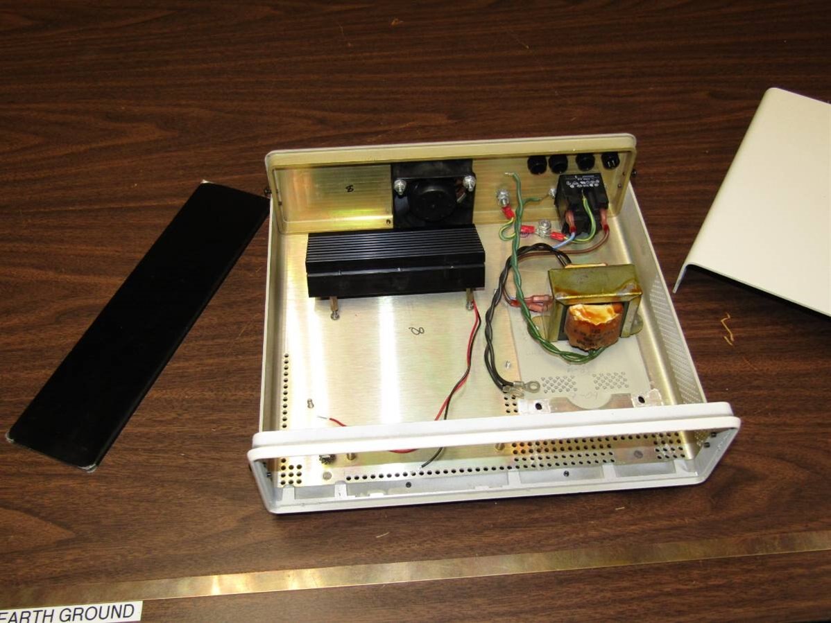
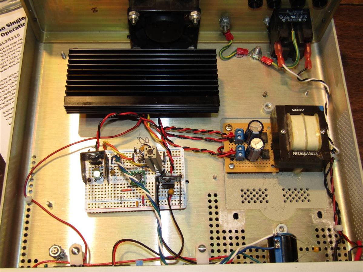
Here is the case I decided to use. The original cast aluminum front panel has been milled out and a black plexiglass panel was cut to fit in its place. The fan and the mains power connector complete with double fused lines came with the enclosure. I was originally looking at using the transformer in this picture but later realized that the power for the ammeter needed to be isolated from the main control circuitry so a transformer with two secondary windings was needed. The large black heat sink will be mounted in front of the fan for best cooling effect.
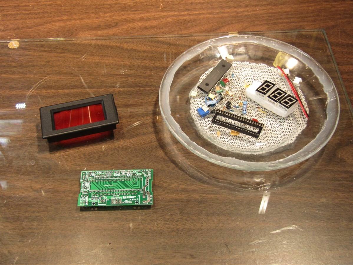
Here is the unassembled Ammeter Kit. I really enjoy assembling these kits. This one has an assembly sequence where half of the CPU socket must be soldered in before the seven segment displays are soldered in. Things get a little stacked and obscured. I mention this as after building 4 of these units I finally got one with a bad 7 segment display. This was discovered after assembly and created a real challenge to fix. Future builds of this kit will include the testing of all segments before soldering. I was able to unsolder 4 of the leads but the other 4 were not able to be reached. My solution was to slowly pry up the display. At $4. I didn't have much to loose. Fortunately one of the leads pulled out of the solder with out damaging the board and the other three broke off. I borrowed a display from another kit and got the ammeter working. Incidentally I tried to find a replacement ss display and could not find one that didn't cost twice as much as another complete kit.
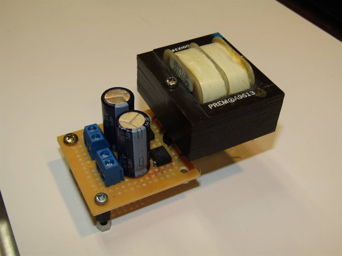
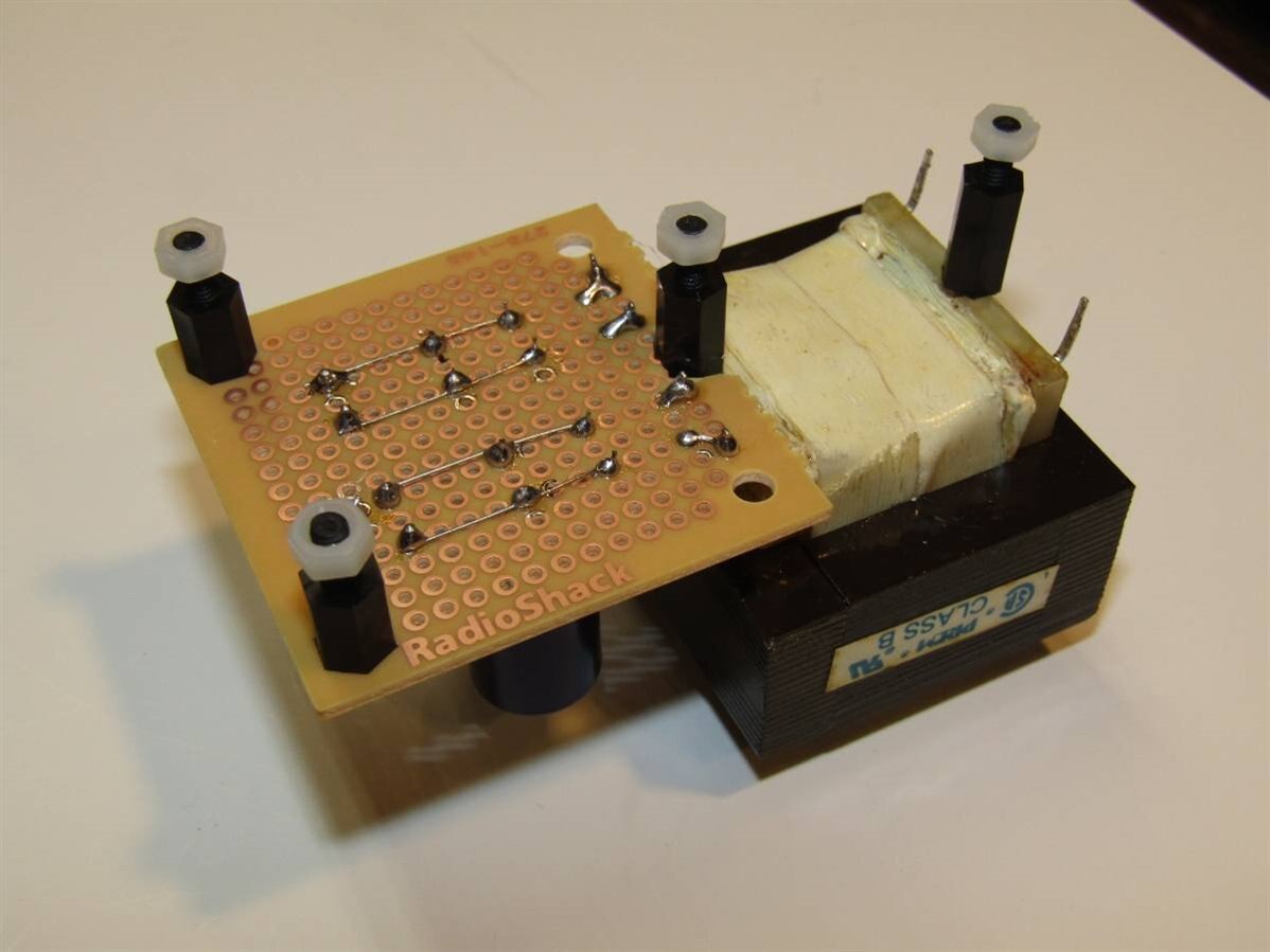
Here is the dual secondary transformer and rectifier board that I eventually decided to use. The secondary AC voltage is 10 V so this will translate to about 14 VDC which is good for running the 12 volt fan in the unit and will provide enough head room for the 7812 drop out of the 12 volt control board supply. The power demands of the circuitry and peripherals are very modest. The Fan draws 35 mA, the ammeter also draws 35 mA, a power indicator LED will draw 5 mA, and the main control circuitry will draw less than 14 mA. This allows the use of small low power components.
One of the beginning activities is to get a general circuit design started and then begin bread boarding and testing the design. I went through a half dozen schematic revisions including a major redesign and rebuild of the control circuit board before the final assembly was possible. Here I am testing and verifying the original ideas:
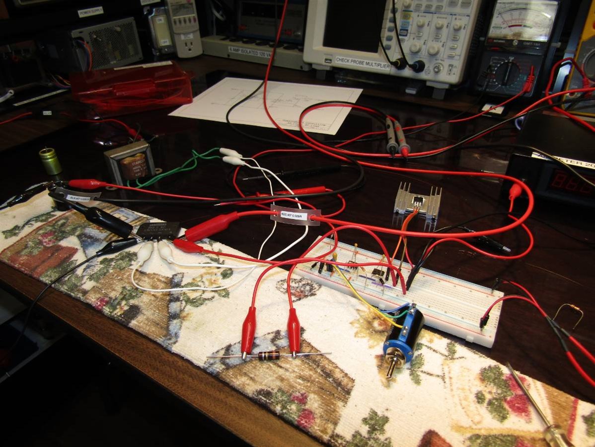
The MOSFET has a temporary home on a small heat sink and the schematic in the background is my general guide. All the testing went well and so I built the circuit board as designed. One of the secrets of building electronics however is that just because everything works great on the bread board is no indication that it will work on a soldered proto board. In some cases the change works to one's advantage with better performance and better stability. Unfortunately this time it was a problem with OSCILLATION. After running a lot of experiments that are not so easy on a soldered board I turned to the vast pool of wisdom here on element 14. I won't rehash the thread where I posted my question as you can check it out if you wish here: Simple Electronic DC Load Conditional Oscillations At first I attempted to fix my flawed design but finally I took the necessary steps and stripped off the first design and put a new one on the proto board. hlipka 's suggestions made a lot of sense as did suggestions from shabaz ,jadew , and mcb1 .

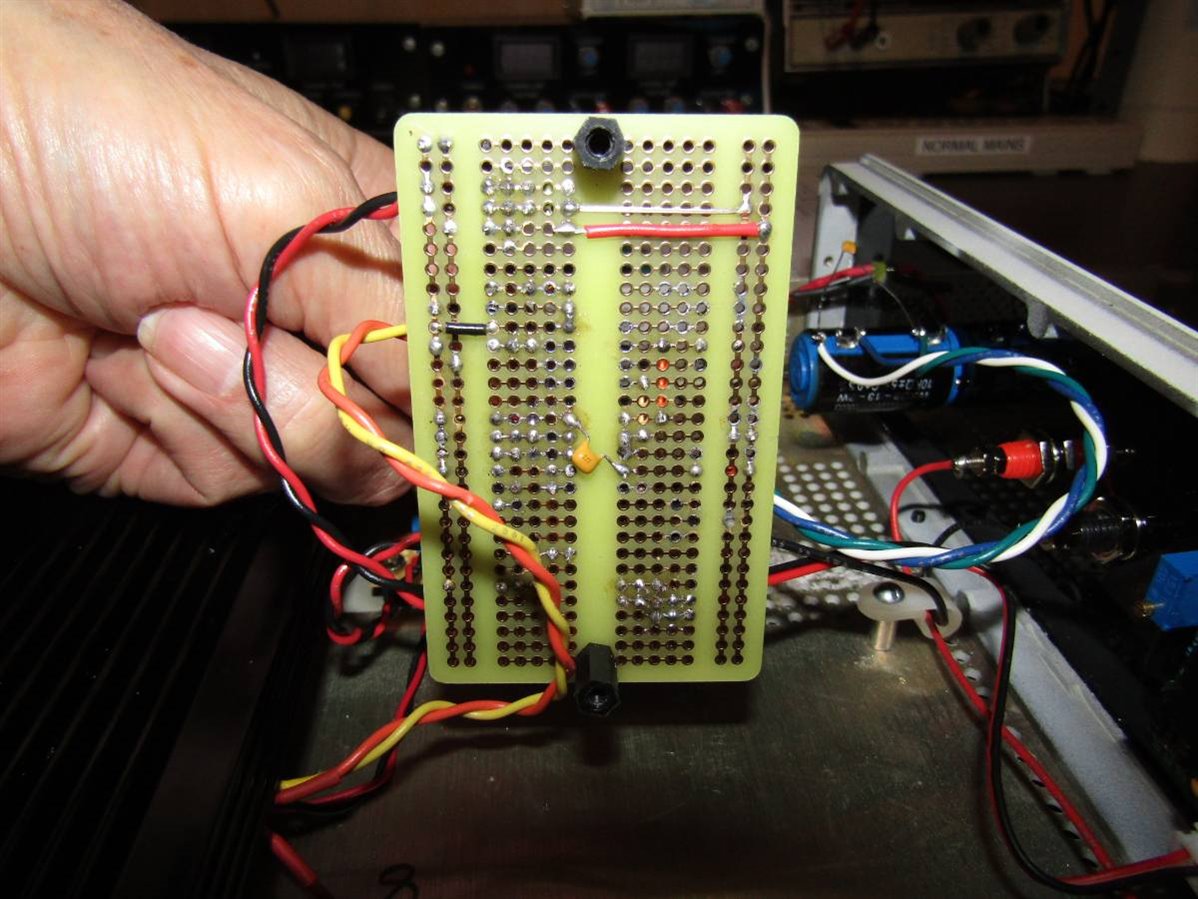
The bread board circuit is being moved onto the proto board. The clip board contains my plan for component layout drawn on graph paper. See I do make a mess on my bench sometimes.
Here are the schematics for the final build as it sits currently on my bench chewing up 100 mA for the last couple hours.


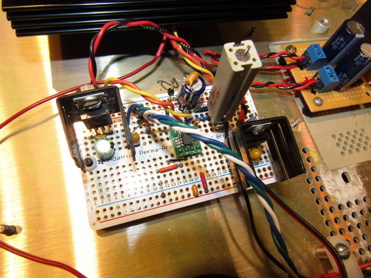
Here is the control circuit board with the regulators for the two power supplies as well. At the power levels that are being used the heat sinks are over kill and in fact I could have probably gotten by with TO92 package regulators. I want to mention that the AdaFruit Prototype boards like this one are excellent. If I have any complaint at all it is that they are too good. When I have to make modifications the gold plated traces conduct heat and the density of the board draws heat away from the pad I am trying to desolder. You may see a strange looking tantalum mounted on top of a couple header pins towards the back right. As I was trouble shooting and experimenting with solving the problem that the unit had with oscillation these pins gave me a place where components could be swapped in and out without going to board level.
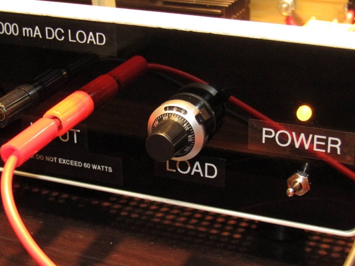
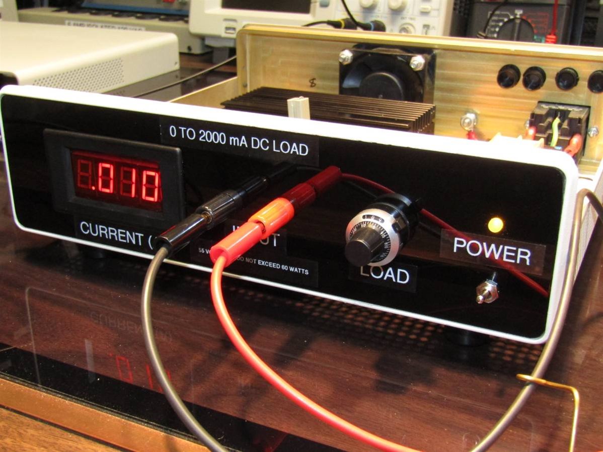
When one buys Chinese 10 turn pots they sometimes supply these neat counter knobs. I have never used one before but this seemed like a good opportunity.
I believe that I once heard a piece of equipment like this one referred to as a "lunch box" due to all the wasted space inside.
It really felt good when the oscillation problem was solved albeit probably in the manner that an old technician might solve it as opposed to a solution by one of the excellent engineers on the forum.
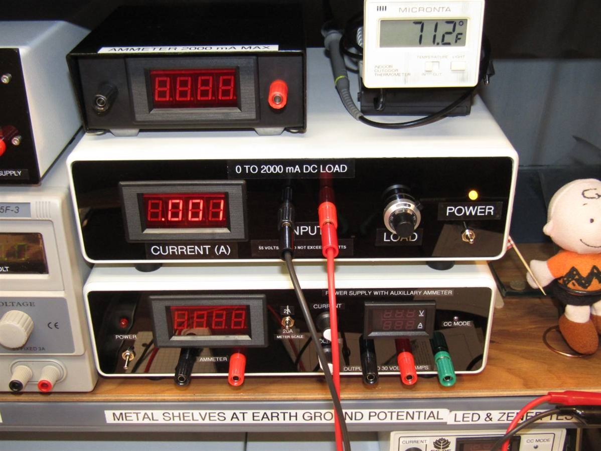
The finished unit sitting with the other builds that have included one of the Chinese Ammeter Kits.
Since I received two suggestions to submit this build to Project 14 I have made a short video of the unit in operation and added it to the end of this blog:
John
Top Comments