


I like to build simple bench test and experimentation equipment, particularly power supplies. Those of you who have been here for a while have had to endure numerous power supply builds from me. My previous builds have been fairly traditional with a mains to operational voltage step down transformer, rectification and filtering, and then a linear voltage and current controller circuit to the outputs. Over the years I have experimented with different variations on this theme. A couple times ago we used mosfets and a controller IC to do the rectification which added almost two volts to the output voltage as there were no diode drops. We have added windings to toroidal transformers in order to hit a target voltage, and we have experimented with different fans and fan control circuitry.
For this power supply build I wanted to step away from the mains to operational voltage transformer and use a switch mode power supply as the source to drive the linear voltage and current control circuit. At first I thought this would be a simple operation and then I discovered that the linear Voltage and Current control circuit relied on the AC input and a voltage inverter circuit to generate a necessary - 5 volt rail. If you are interested in how this problem was solved you can check out my blog:
https://www.element14.com/community/people/jw0752/blog/2018/11/10/exploring-the-recom-rh-2405d
The experiments with the Recom RH 2405D allowed for a redesign of the linear control circuit that made my move to a SMPS for the base voltage supply possible.
The Switch Mode Supply that I wanted to use in this power supply was a medical grade Protek PM110 which I had salvaged from a piece of dental equipment. The model that I had was preset to 24 Volts.

While 24 volts would work the limit on the input for the linear controller was 34 Volts so if possible I wanted to see if I could hack the Protek to see if I could boost its output voltage. There was a resistive trimmer on the voltage control board but it only allowed a +/- 1 volt adjustment. After studying the board I found a sense circuit leading back from the output to the control board and by manipulating the resistor in this circuit I was able to get the unit to put out 30 Volts. I would have been very happy with this level of voltage but I was apparently pushing the unit to its design limits as it was not stable at this level and would occasionally fall into its protection mode when first powered up. I backed off my hack so that the output voltage of the Protek was 28 volts and this remained stable. I tested the supply by loading it to 4 amps and letting it run for 20 minutes. The supply remained operational and stable. The max current that the linear controller board will process before limiting the current is a little over 3 Amps so I had a source of voltage, the Protek SMPS, that would be adequate for the task. In the picture above you can see where I removed a series sense resistor from the board and patched in a small trimmer so that I could adjust the output voltage. When I finally had things working the way I wanted I remove the trimmer and replaced it with a fixed resistor of the same value.
The case that I wanted to use for this power supply was fairly large and so I decided to extend the concept for this new build to include a second switch mode power supply (SMPS) with multiple fixed voltages on its output. I looked through the salvage box and located a Condor GPM55 that had also come out of a piece of dental equipment. This particular supply had the following outputs: -12 Volts at 1 A, +12 volts at 3 A, and +5 Volts at 6 A. By adding one more stage to this SMPS in the form of a small 3.3 volt DC to DC converter I hoped to cover a good selection of popular voltages. Further by creating an isolated common between the fixed voltage section and the variable voltage section of the supply I would be able to add and subtract voltages as well as create +/- combinations as needed. On the completed unit you will note that there is a Common 1 and a Common 2.
At this point I had all the parts that I would need for the build except the front panel. Due to the number of meters and other things that needed to be mounted on the front panel I hoped to find a place to laser cut my design so that I would not have to spend hours with the drills, scroll saw, and files. The local Makers Space where I had laser cut my panels in the past had closed down and my inquiry on the forum gave me some good long term ideas but not an immediate solution so I bit the bullet and had the cutting done by a commercial laser cutting company.
When I build a project like this I enjoy the planning and preliminary work as much or more than the actual assembly. I enjoyed drawing the front panel with a computer drawing CAD. I am not very good at using it but I can usually find my way slowly. I showed the drawing program to one of the grandkids last weekend. His name is Christian, he is 12 and has a mathematical mind. A half hour after he started playing with the drawing program he began teaching me new things about it that I hadn't figured out for my self yet. It was a humbling experience.
I also like to plan the wiring and draw the schematics. Since I have used the linear controller board many times I have reverse engineered it and drawn its schematic as well as taken empirical node voltages at standard settings so that I have a good baseline in case one needs to be repaired. This build was extra fun as the linear board had to be hacked and modified to produce the negative five volt rail and a new modified schematic needed to be produced.

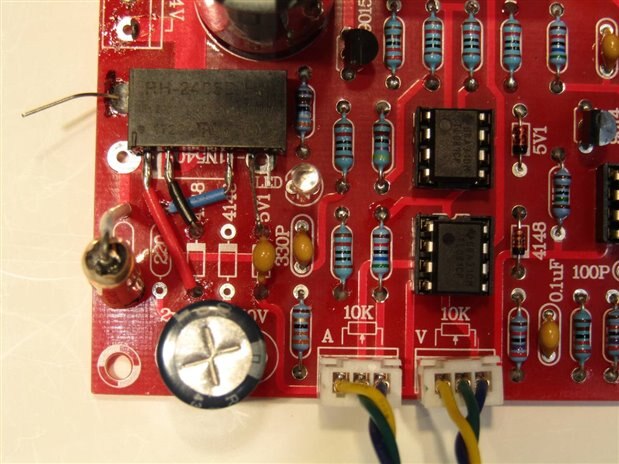
This is the section of the linear controller board where the Recom RH 2405 was installed.
Since the SMPS modules were only going to be used for this one project I did not draw any schematics for them but instead produced an over all schematic for the new supply with the SMPS units drawn in as black boxes.

Once the circuit is drawn out in this manner it is easy to see just how simple it is overall. Part of my concept for the build was to place small Chinese voltmeters on the control panel between each of the output binding posts. I wanted these displays to have similar display brightness so each unit was powered from one of the 12 volt supply lines. The larger volt / ammeter for the variable section would get its power from the previously unused +5 volt rail of the Recom RH 2405.
With the plans all in hand and the parts in a box it was finally time to start putting things together. I have to confess that once I start this process I loose track of time, the rest of the world, and usually the need to take pictures of the progress. Here are some pictures but not much assembly detail.
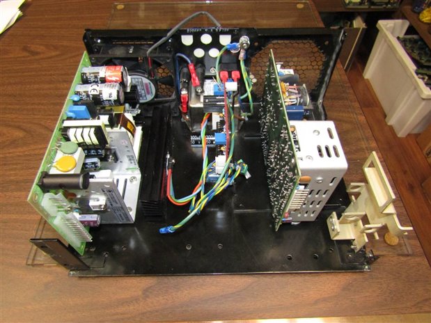
This is the case of the supply with the SMPS units mounted and the linear control board in the middle. It is difficult to see, black on black, but there is a good aluminum heat sink for the output transistor of the linear control board mounted to the chassis between the linear board and the SMPS on the left. Directly behind the heat sink and the SMPS is a fan that moves air into the unit where it circulates around the units and exits on the back right side.
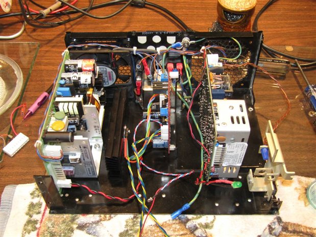
In this picture I have begun to add the wiring between the modules as well as the mains connections to the boards.
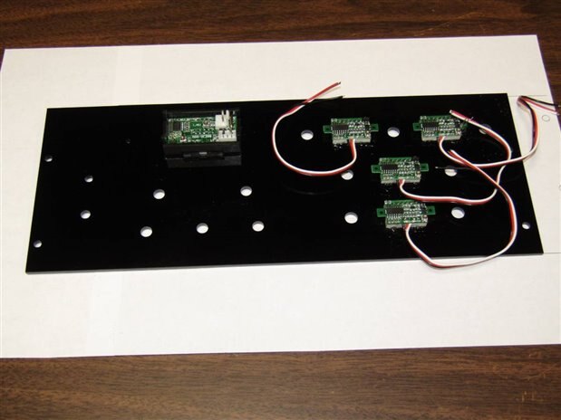
With the arrival of the front panel from the laser cutters I have begun to assemble the meters into the board. The truth be told I made 5 mistakes in my drawing of the front panel. With the cost of $70 for this item I was extremely lucking that none of the mistakes were fatal. The mistakes put me to work with a drill and some files but in the end they were not a real problem. I have made a note to myself to be more careful and to take the time to carefully recheck my next drawing prior to sending it off for an expensive cutting.
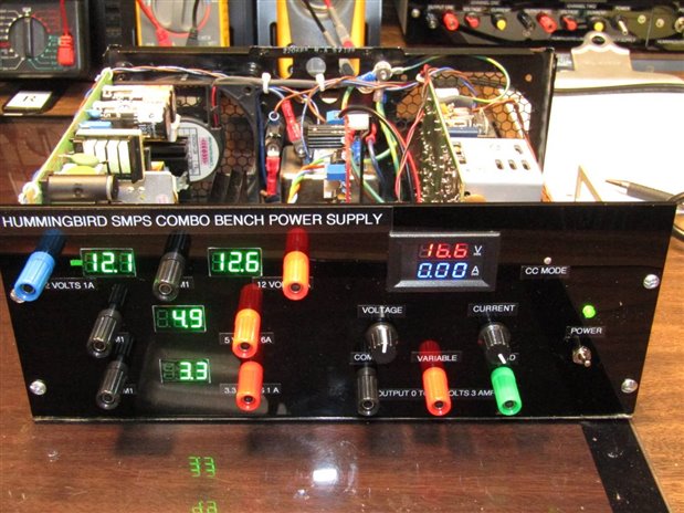
Here is what the operational unit looked like when I first turned it on. At this point the unit must be calibrated so that the voltages on the meters are as close as possible to actual voltages and currents. The next test will be to put loads on 2 or 3 channels simultaneously and let the unit run for a while to make sure there are no problems.

Here is a picture of the unit looking from the back towards the front panel. At this point wires have been bundled. This picture gives a little better view of the heat sink that we mentioned before.
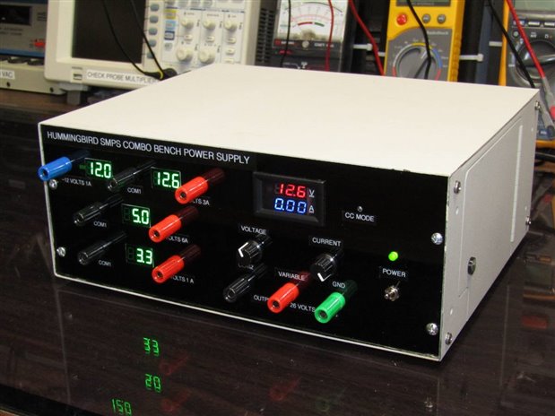
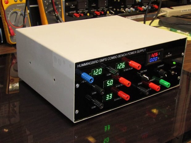
Finally we have the completed unit inside its case and operational. One of the side effects of using salvage parts and cases is that you end up with delightful but totally unnecessary little doors from time to time. The door on the right side of the case is one such example. It was a access door for the original inhabitant of the case where an arc lamp could be replaced. The two holes on the left side of the case were for a handle as the case was originally designed as a vertical enclosure.
John
Top Comments