element14 Community
element14 Community
    Register Log In
  • Site
  • Search
  • Log In Register
  • Community Hub
    Community Hub
    • What's New on element14
    • Feedback and Support
    • Benefits of Membership
    • Personal Blogs
    • Members Area
    • Achievement Levels
  • Learn
    Learn
    • Ask an Expert
    • eBooks
    • element14 presents
    • Learning Center
    • Tech Spotlight
    • STEM Academy
    • Webinars, Training and Events
    • Learning Groups
  • Technologies
    Technologies
    • 3D Printing
    • FPGA
    • Industrial Automation
    • Internet of Things
    • Power & Energy
    • Sensors
    • Technology Groups
  • Challenges & Projects
    Challenges & Projects
    • Design Challenges
    • element14 presents Projects
    • Project14
    • Arduino Projects
    • Raspberry Pi Projects
    • Project Groups
  • Products
    Products
    • Arduino
    • Avnet Boards Community
    • Dev Tools
    • Manufacturers
    • Multicomp Pro
    • Product Groups
    • Raspberry Pi
    • RoadTests & Reviews
  • Store
    Store
    • Visit Your Store
    • Choose another store...
      • Europe
      •  Austria (German)
      •  Belgium (Dutch, French)
      •  Bulgaria (Bulgarian)
      •  Czech Republic (Czech)
      •  Denmark (Danish)
      •  Estonia (Estonian)
      •  Finland (Finnish)
      •  France (French)
      •  Germany (German)
      •  Hungary (Hungarian)
      •  Ireland
      •  Israel
      •  Italy (Italian)
      •  Latvia (Latvian)
      •  
      •  Lithuania (Lithuanian)
      •  Netherlands (Dutch)
      •  Norway (Norwegian)
      •  Poland (Polish)
      •  Portugal (Portuguese)
      •  Romania (Romanian)
      •  Russia (Russian)
      •  Slovakia (Slovak)
      •  Slovenia (Slovenian)
      •  Spain (Spanish)
      •  Sweden (Swedish)
      •  Switzerland(German, French)
      •  Turkey (Turkish)
      •  United Kingdom
      • Asia Pacific
      •  Australia
      •  China
      •  Hong Kong
      •  India
      •  Korea (Korean)
      •  Malaysia
      •  New Zealand
      •  Philippines
      •  Singapore
      •  Taiwan
      •  Thailand (Thai)
      • Americas
      •  Brazil (Portuguese)
      •  Canada
      •  Mexico (Spanish)
      •  United States
      Can't find the country/region you're looking for? Visit our export site or find a local distributor.
  • Translate
  • Profile
  • Settings
Personal Blogs
  • Community Hub
  • More
Personal Blogs
John Wiltrout's Blog Auxillary Variable Bench Power Converter
  • Blog
  • Documents
  • Mentions
  • Sub-Groups
  • Tags
  • More
  • Cancel
  • New
  • Share
  • More
  • Cancel
Group Actions
  • Group RSS
  • More
  • Cancel
Engagement
  • Author Author: jw0752
  • Date Created: 2 Oct 2014 5:52 AM Date Created
  • Views 525 views
  • Likes 2 likes
  • Comments 8 comments
  • bench
  • converter
  • john
  • wiltrout
  • supply
  • power
Related
Recommended

Auxillary Variable Bench Power Converter

jw0752
jw0752
2 Oct 2014

After recently completing a simple regulated 0 to 30 volts DC variable power supply for my bench,  See: "A New Power Supply for John"  I realized that the job was only half finished. What about the times when I would need a second voltage for an experiment or if my project would need a split plus and minus voltage supply. Obviously I needed another source of variable power to supplement the new power supply.


I began by taking stock of my resources and planning the new addition around a couple components and concepts. First of all I wanted this unit to be small and portable so that I could move it around. Since I already had 2 non-regulated variable supplies besides the new regulated supply,  I decided to make this unit an auxiliary that would plug into one of the non-regulated supplies. Therefore what I would be building would be a variable regulator and in keeping with the simplicity of the other supply it was decided that I would use the familiar LM317 regulator and a support circuit taken from the data sheet. One component that I wanted to use for this project was an $11 Digital Volt Ammeter that I had purchased from China.


                                                                           image


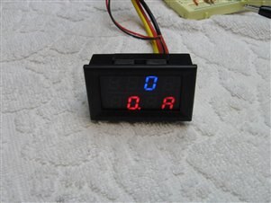
My previous experience with this unit had taught me, with a plume of smoke, that while it would display up to 99.9 volts and 99.9 amperes it would not tolerate more than about 28 volts for its power supply. I decided to include in my circuit design a 7812 regulator to provide power for the V/A meter and that I would also bring this regulated voltage out to the front panel since it was already available. After putting together a couple prototypes on the bench and running tests to see that things would work as I wanted them to I had a good  handle on the final circuit. Here is a schematic of the final version of the circuit.


                                image


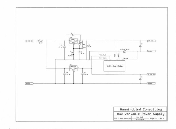
As you can see there is nothing complicated about the design and it will provide adequate regulation and current for the type of projects that I typically work on. The wiring from the Chinese V/A meter is color coded but you can not trust it. The unit that I received had the large red and yellow wires exchanged but over all it was not hard to figure out. One of the things I like the most about buying things like the Chinese V/A meter is the challenge that comes with circuits that come with little to no documentation or explanation. Furthermore my wife calls this source of gadgets the Chinese Dollar Store, which means that I am only risking minimal dollars if there is a failure.


I began the actual build by mounting the LM317 and the 7812 to a piece of salvaged heat sink. I then used a small universal circuit board to mount the regulators and related circuit components. When I had it built for preliminary testing it looked like this.


         imageimage


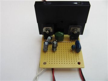
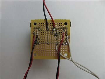
The additional portion of the circuit board that was not used was eventually cut off to make for a better fit in the enclosure. At this stage I again set up proto connections to verify that I had hooked things up as planned. I have learned that if I do not do this as I go along I just have to disassemble my project later and fix what I missed.


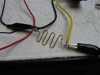
My next big challenge was to test and calibrate the Volt Ammeter. It was designed to be used with a big honking shunt that would allow it to work in the 100 amp range. My planned circuit would top out at 28 volts and a couple amps. The volt reading would take care of itself as my tests had revealed that it was in agreement with my Fluke multimeter to 0.10 volt. This was within tolerances for my needs. To bring the ammeter into line I had to build a special shunt. I wanted to get as much accuracy as possible in my working parameters of 0 to 3 amps. I took a piece of brass wire and with a known current flowing slid the meter contact down the brass wire until the display of the digital meter matched the known current. The only problem at this point is that the ammeter read 10.0 amps when the actual current was 1.00. At first I planned to do some work on the digital meter's circuit to try to move this decimal point but after seeing that the display, including the decimal point, was being strobed by the driver circuit I decided on a more manual approach. I used black paint to darken the lit LED decimal point segment and painted a white dot on the display where I wanted the decimal point.


                                                                    image


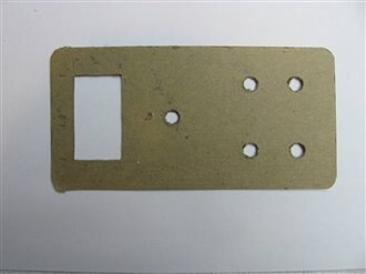
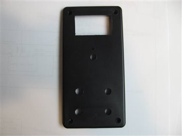
I planned to put the circuitry into a plastic case 15cm X 7cm X 5cm. I always make a template out of cardboard or other soft material so that I can have the best chance of properly positioning my peripherals before I start drilling and filing. My tools include a drehmel, files, hand drills, and other simple tools. This is the hardest part for me as I am a bit of a specialist in having drills walk away from my intended drilling site and I also specialize in slipping and scratching what should not be scratched. This time I was fairly lucky and was able to cover up my mistakes with a little file work.


                               imageimage


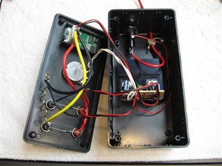
I now began to mount the jacks, meter, potentiometer, fuse holder, and drilled the circuit mounting hole in the back and input wire access hole. If you ever work with one of these Chinese meters it is important to remove the circuit from the bevel before inserting it through the hole as the retention clips will not retract with the circuit installed. I also filed the bevel of the meter so that it was a little bigger as it obscures the lower segments of the display from the supplier. Here is a picture of the internals after the wiring was complete.


                                     imageimage


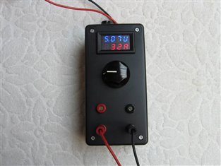
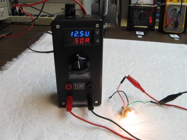
Now all that was left was to label the unit and run it through some tests. I connected it up to my old unregulated EICO power supply and loaded it with a 12 volt automotive tail light. I have found light bulbs to make good safe loads with which to test circuits. I do not have the worry about burns or fire that I would have using resistors. I ran the unit for an hour with a load of 0.50 amps and 12.5 volts being driven by the EICO at 20 volts. It got warm and stabilized. As this is was more current and a longer time than I would typically need I was satisfied with the results. Here is a picture of the finished unit.


                                           image


John

  • Sign in to reply
Parents
  • D_Hersey
    D_Hersey over 10 years ago

    Really nice job.  I made something like this, sadly without your attention to finishing details, built it on a piece of lumber in point of fact.  Embarrassingly, I wound up using it for years and years.  The dual display is nice.  Analog needle displays might make a nice adjunct as they are more intuitive and can be interpreted more quickly.  Of course, they can operate in parallel to your digital displays.   Amused by your mechanical sliding of the decimal point.  Auto-scaling  displays can cause the mistake of 'slipping a DP' or two, causing me to inadvertently construct an X-ray machine awhile back.

    Kudos!


    Did you use a drill or a step-drill to make your holes?  Also, BTW, I happen to have access to gads of CNC equipment should you want to make a metal box on another project and be certain of a one-shot deal.


    Nice schematic too, how'd ya' draw it?


    That ABS box is pretty but the problem I found in working them is that the material is soft.  In metal, you can scratch a little cross-hair where you want the hole, then use a spring-loaded punch to get the party started.  The ABS would rupture, and it isn't hard enough relative to the cutting tools to support them accurately.  If you drill small pilot holes, you can put a step drill in subsequently to enlarge them if they are accurately placed.  If you missed a little, you can use a pointy round file to scooch the hole into place, then return to the party with the step drill.

    • Cancel
    • Vote Up 0 Vote Down
    • Sign in to reply
    • More
    • Cancel
Comment
  • D_Hersey
    D_Hersey over 10 years ago

    Really nice job.  I made something like this, sadly without your attention to finishing details, built it on a piece of lumber in point of fact.  Embarrassingly, I wound up using it for years and years.  The dual display is nice.  Analog needle displays might make a nice adjunct as they are more intuitive and can be interpreted more quickly.  Of course, they can operate in parallel to your digital displays.   Amused by your mechanical sliding of the decimal point.  Auto-scaling  displays can cause the mistake of 'slipping a DP' or two, causing me to inadvertently construct an X-ray machine awhile back.

    Kudos!


    Did you use a drill or a step-drill to make your holes?  Also, BTW, I happen to have access to gads of CNC equipment should you want to make a metal box on another project and be certain of a one-shot deal.


    Nice schematic too, how'd ya' draw it?


    That ABS box is pretty but the problem I found in working them is that the material is soft.  In metal, you can scratch a little cross-hair where you want the hole, then use a spring-loaded punch to get the party started.  The ABS would rupture, and it isn't hard enough relative to the cutting tools to support them accurately.  If you drill small pilot holes, you can put a step drill in subsequently to enlarge them if they are accurately placed.  If you missed a little, you can use a pointy round file to scooch the hole into place, then return to the party with the step drill.

    • Cancel
    • Vote Up 0 Vote Down
    • Sign in to reply
    • More
    • Cancel
Children
  • jw0752
    jw0752 over 10 years ago in reply to D_Hersey

    Hi Don, It is really good to hear from you. Thanks for your comments. I used a regular drill as I had one very close to the required size but I also have a step drill that I can and like to use for larger holes. The drilling of pilot holes is important and probably why my layout is as close to proper as it is but even with the pilot holes I often find the bit will walk to one side or the other. If I did a lot of this type of work I can see the advantage to getting a cheap drill press. I put analog meters on the larger power supply that I built a couple weeks ago and I too have an affinity for the dial meters as this is what I grew up with. Using the digital meter was my attempt to move a little closer to modern electronics and to keep the supply small. The schematic was drawn with software provided by Express PCB. They provide the software hoping that the user will order PCBs from them. It is a simple program and well suited to small simple schematics and I have gotten used to it. While their file seems to be only readable by their program I just take the print and rescan it into JPEG for posting to the forum. I will keep the CDC boxes in mind, Thanks.

    John

    • Cancel
    • Vote Up 0 Vote Down
    • Sign in to reply
    • More
    • Cancel
  • D_Hersey
    D_Hersey over 10 years ago in reply to jw0752

    The story on the CNC equipment is that a school-chum of mine was attending JUCO.  He had a good business as an auto and machine repairman, but had a coupla motorcycle accidents and became less able to perform at this.  So he went back to school at 45.  Caught on, found some work there as well teaching some machining classes.  The event was Obama et al bathed them in money.  They are erecting a facility that is intending to represent every market-significant method of fab, current and future, in large format.  Claims to be busier than a one-armed wallpaper-hanger.  Besides the usual mill-turn-grind set-up, they are getting stuff like hybrid waterjet/laser/EDM cutters, welding robots, additive machining facility, just everything.  It will be a coupla months before everything is levelled and the dust settles, then it will be files-to-stuff, lickety-split!

    • Cancel
    • Vote Up 0 Vote Down
    • Sign in to reply
    • More
    • Cancel
element14 Community

element14 is the first online community specifically for engineers. Connect with your peers and get expert answers to your questions.

  • Members
  • Learn
  • Technologies
  • Challenges & Projects
  • Products
  • Store
  • About Us
  • Feedback & Support
  • FAQs
  • Terms of Use
  • Privacy Policy
  • Legal and Copyright Notices
  • Sitemap
  • Cookies

An Avnet Company © 2025 Premier Farnell Limited. All Rights Reserved.

Premier Farnell Ltd, registered in England and Wales (no 00876412), registered office: Farnell House, Forge Lane, Leeds LS12 2NE.

ICP 备案号 10220084.

Follow element14

  • X
  • Facebook
  • linkedin
  • YouTube