


This is the first time that I have encountered the concept of 'LED Amplifier'. I did not even know what it was until the situation presented itself and I knew that it was what I needed to solve the latest challenge from my Mom. Let me back up a little as you may have not read some of my previous blogs. My Mom is in a nursing home with a disease that is slowly stealing her ability to move, talk, and enjoy life. As her condition has worsened I have tried to use technology to ameliorate her situation.
The latest problem involves her Call Button System. There are two ways that Mom can summon help when she needs it. If she is in bed or her recliner she has a corded push button that she can press which lights a small light on the control center in her room and also a larger light in the hall outside her room. If she is in her wheel chair I have mounted a wireless button on the chair that can also trigger the lights that summon help. Here is a picture of the control center in Mom's room.
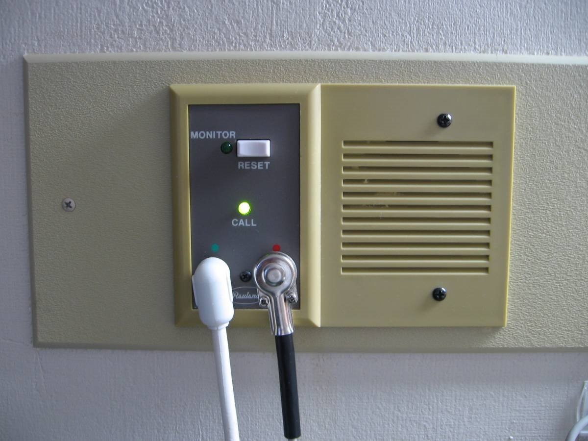
Once she has pushed her button the only way she can see if the alert has been triggered is to see if the small green LED is lit. Since she can no longer move her head or her body I have rigged some mirrors that allow her to see the light behind her on the wall when she is in the wheel chair. However if she is in the bed or the recliner the light is just too far away or at the wrong angle to see in the mirrors. The other day she explained to me that she thought she had pushed the button and after waiting for over an hour, someone checked on her. When she asked why it had taken so long they acted surprised and told her that her light had not been on. She asked me if there was some way to know if the call light was lit or not. Ideas began to come to my mind. Here is what the Green LED looks like in the normal lighting of her room.
.
I decided that what would be needed would be a way to amplify the intensity of the LED. The nursing home has strict rules about modifying any of their equipment so I always have to work with what is there and can not tap into the system. I also wanted to make the new amplified LED flash or oscillate between two colors so that it would be more noticeable. As soon as I got back to my shop I began bread boarding some possible circuits and testing for proof of concept. You will all recognize the simplicity of the circuit I put together. One of the things that I have found is that often the best solutions to a problem are also the simplest. Here is the schematic of the final design for my LED Amplifier:

The input sensor for the amplifier is a phototransistor which in this case is a TEPT5600TEPT5600 The phototransistor is housed in a small pillar so that when mounted to the control panel in Mom's room it will look directly at that green LED The output of the phototransistor controls the base of a small NPN transistor When the phototransistor sees light it pulls the base of the 2N22222N2222 high and turns on the transistor which in turn increases the current to a small two color LED IC The LED alternately flashes Red and Blue at an intensity several times that of the original Green LED The power for this system comes from 4 AA batteries One of the things that are in short supply in Mom's room are mains outlets Basically for their insurance reasons I am not allowed to plug any of my mutant devices into the mains power That is OK as the current consumption of the LED amplifier is low enough so I can expect several months of OFF time and perhaps 10 hours of ON time before the batteries need replacing I will be able to know when the batteries are getting low as the Blue LED takes more voltage than the Red one and so as soon as the Blue no longer lights it will be time for new batteries Here are some of the pictures that I took during construction of the unit
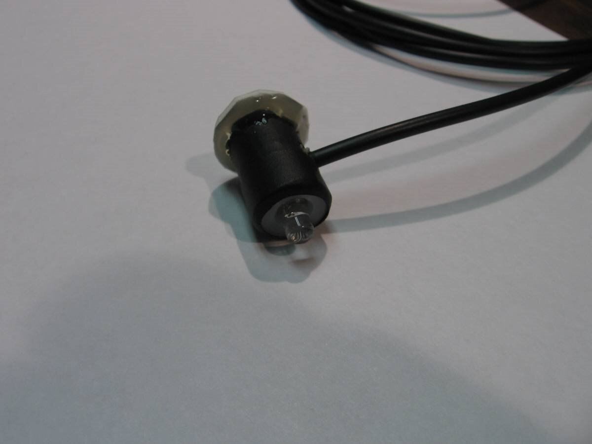
This is the top of the pillar showing the Red - Blue Flasher IC LED. On the other end you can see the ring of double sided tape which will hold the pillar over the Green LED of the control panel.

Here is the bottom of the pillar with the phototransistor looking out the hole with just enough clearance so the Green LED can fit inside the hole nose to nose with the Phototransistor. The wire that I used is a small 2.5 mm cable that is used for headphone extensions and has a Red, Black, and White conductor. Since we are only going a short distance I did not use a shielded cable. I had concerns as it was about the weight of the cable creating stress on the mount of the pillar.

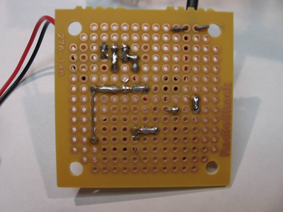
Here are the front and back views of the circuit board complete with labels. (No surprise). The wires at the top back view are strain relief and I did not solder them as the heat would have caused it to cut into the cable insulation.
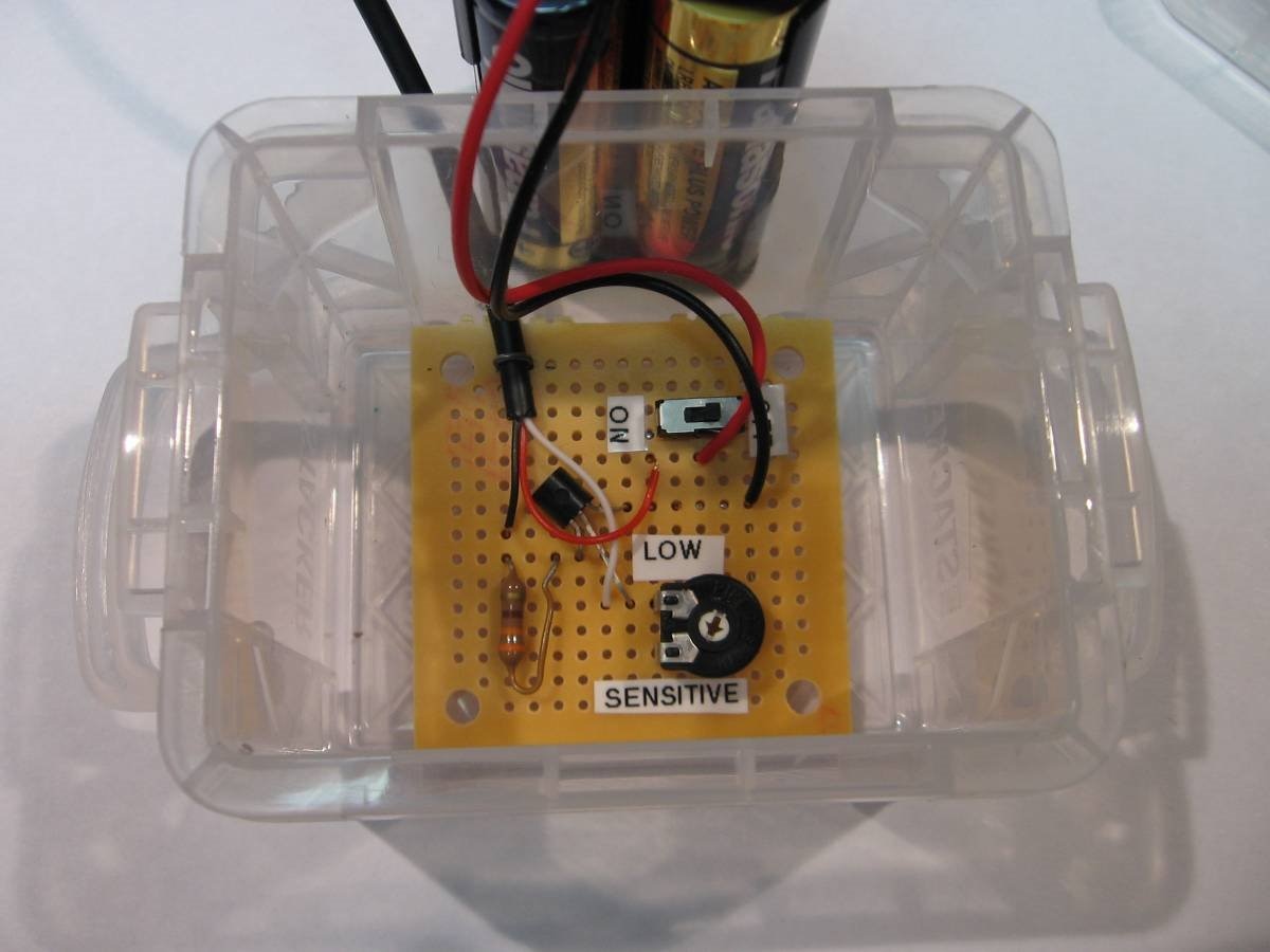

A small plastic box was found to house the circuit board and the battery. All that was left was to install it in Mom's room and see if it works as hoped.
Here is a short video of the unit being tested.
While all seemed fine to me I didn't celebrate until Mom called several hours later to say it was working perfectly.
John
.
Top Comments