


While checking out the source of all things economical I came across this frequency counter kit and crystal tester.
Yes the price was only $7.45 and they insisted on shipping it for free. I did not expect much, but for $7.45 there is nothing to loose and if I could make it work it would be handy for testing salvaged crystals and showing the frequency of some of the little oscillator circuits that Grandson Ivan and I are putting together for practice bread boarding.

The kit came with a nice well made circuit board and all the needed components but there was a real lack of literature. I was not worried about assembly instructions as the screening on the board was very self explanatory but operational instructions were another matter. As I began to assemble the unit, I would take breaks and search the internet for more information on this particular design. After a little research I discovered the designer of the circuit was Wolfgang "Wolf" Buescher who is a HAM Radio operator, Call Sign DL4YHF. Apparently the Chinese marketers of this kit had appropriated the design without Wolf's permission or giving credit where credit was due. Wolf who is a really great guy was forgiving particularly since the price being charged was reasonable and he had originally put the design out open source. I decided that before blogging about this kit I would email Wolf and get his permission and give him credit for a great little practical circuit. Here is Wolf's Web Site and the back ground information on the original build using a PIC 16F628A processor. If someone wants a bigger challenge than just a kit it would be possible to build this unit from Wolf's original design. With Wolf's permission in hand I will proceed with the build.
http://www.qsl.net/dl4yhf/freq_counter/freq_counter.html
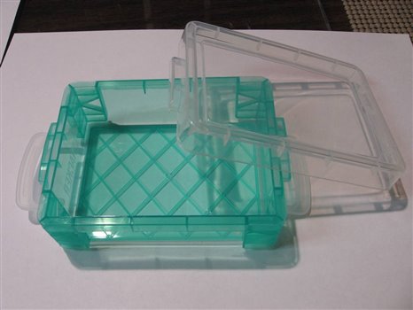
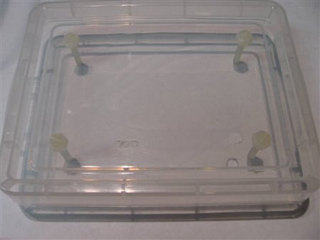
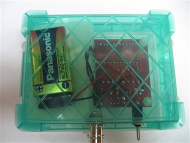
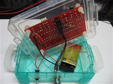
I checked my pile of project enclosures and found a small plastic box that I had purchased at the Walmart for about $2.00. It looked like a perfect fit for the circuit and the peripheral jacks and switches. Here is a picture of the project box and the raw board:

Before I began the assembly of the components I used the raw circuit board to mark the mounting hole in the top of the project box. I also marked the position of the crystal jack, which I wanted to come through the top as well as the location of the hole for the program button. The next step would be to build the unit and begin the testing before I went to the trouble of fitting it into the project box. I decided to power the unit with a 9 Volt battery so I left the DC jack off and wired directly to a battery clip and a small SPST toggle switch.
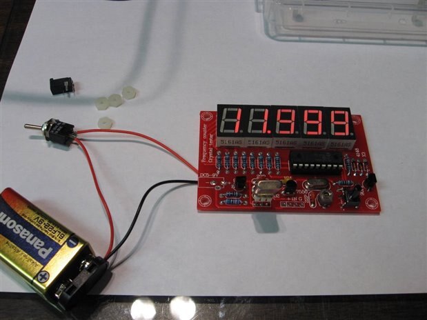
Here we can see the circuit reading a 12 MHz crystal in the initial test.
The first night I was able to get the unit to work with several salvage crystals that I had in my bin. However the unit would not accept signals from the Waveform Generator. As it was very late at night, or should I say very early in the morning, I decided to quit for the night and let my brain work on prospective experiments that I could run to further check out the unit and get it completely working as designed. The next night I returned refreshed and got down to work checking things out. I used the oscilloscope to check the wave form and the voltage of the output of the internal crystal tester oscillator as it entered the #3 input pin of the PIC. This was found to be 9.6 volts peak to peak. I reconfigured the wave form generator to these parameters and tried the input of the counter again. This time everything worked fine. Last night it seems I had been too conservative in my input voltage. A quick test of limits revealed that the circuit would not work if less than 7 Volts PP ( 2.45 V rms) is applied to the input). Since the Oscillator was supplying about 10 V PP (3.5 V rms). I will begin with the assumption that this as a safe operating range. It will be important for me to find out what is the input voltage limit for the PIC. Since the unit has the input tied, unbuffered, directly to the input pin I am concerned that a spike or excess input voltage could damage the PIC. Further testing revealed good accuracy of the frequency tester between 1 Hz and 25 MHz which is the top limit of my signal generator. Specifications on the kit claim a range of 1 Hz to 50 MHz but I am not able to verify this.
With the satisfactory initial tests I proceeded to cut the mounting and access holes into the plastic of the top. This box is made of a fairly soft poly plastic. If the hole needed is small enough a sharp twist drill bit works well but for larger holes I have not found a really satisfactory method to make a nice clean hole. Any ideas on how to cut holes in this type of material would be appreciated. It I cut it with a high speed cutter it melts the plastic and makes a mess of splatter. If I try to ream the plastic it just deforms and wraps around so that I have to use an xacto knife to clean up the edges of the hole after it is made. If I use a twist drill that is to large it cracks the plastic. Perhaps some sort of hole punch would be best but the ones that I have will not reach deep enough into the work area for this project.

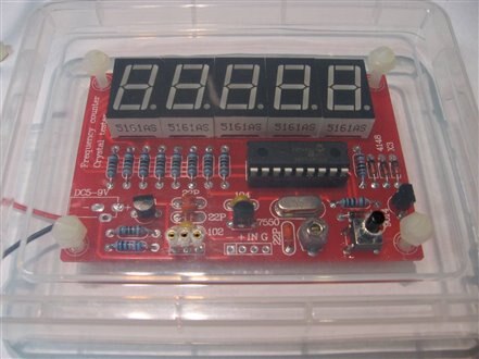
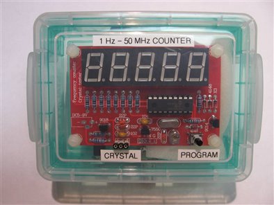
Here is the completed unit, before labeling, testing a 10 MHz crystal. For the crystal test socket I used a header riser to bring the pin jacks up to and through the front panel. A second 3 pin header was then plugged into the first to give a raised, accessible crystal test socket.
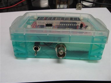
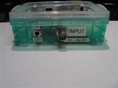
Three views of the completed project, still without labeling.
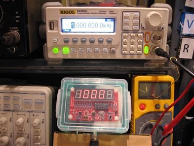
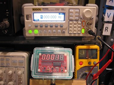
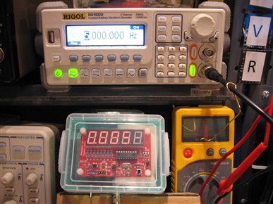
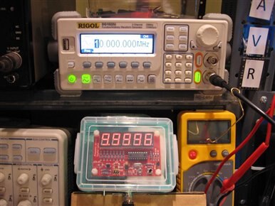
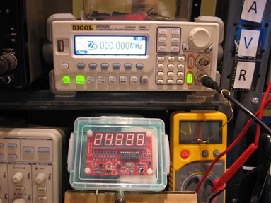
Here are a series of tests showing the range of the frequency counter and its accuracy. Note that the decimal point of the little counter flashes if the output in displayed in kHz and remains steady if the display is in MHz. With the testing completed the only thing left is to get out the trusty label machine and finish the job.

This was a really fun project with a total over all cost for parts in the area of $15.00 USD. It is working well within the accuracy that I consider acceptable for a hobby shop such as the one I have. If you decide to make one for yourself, be sure to check out the link to Wolf Buescher's Web Site for more detailed information on the circuit and how it works.
John
Top Comments