element14 Community
element14 Community
    Register Log In
  • Site
  • Search
  • Log In Register
  • Community Hub
    Community Hub
    • What's New on element14
    • Feedback and Support
    • Benefits of Membership
    • Personal Blogs
    • Members Area
    • Achievement Levels
  • Learn
    Learn
    • Ask an Expert
    • eBooks
    • element14 presents
    • Learning Center
    • Tech Spotlight
    • STEM Academy
    • Webinars, Training and Events
    • Learning Groups
  • Technologies
    Technologies
    • 3D Printing
    • FPGA
    • Industrial Automation
    • Internet of Things
    • Power & Energy
    • Sensors
    • Technology Groups
  • Challenges & Projects
    Challenges & Projects
    • Design Challenges
    • element14 presents Projects
    • Project14
    • Arduino Projects
    • Raspberry Pi Projects
    • Project Groups
  • Products
    Products
    • Arduino
    • Avnet Boards Community
    • Dev Tools
    • Manufacturers
    • Multicomp Pro
    • Product Groups
    • Raspberry Pi
    • RoadTests & Reviews
  • Store
    Store
    • Visit Your Store
    • Choose another store...
      • Europe
      •  Austria (German)
      •  Belgium (Dutch, French)
      •  Bulgaria (Bulgarian)
      •  Czech Republic (Czech)
      •  Denmark (Danish)
      •  Estonia (Estonian)
      •  Finland (Finnish)
      •  France (French)
      •  Germany (German)
      •  Hungary (Hungarian)
      •  Ireland
      •  Israel
      •  Italy (Italian)
      •  Latvia (Latvian)
      •  
      •  Lithuania (Lithuanian)
      •  Netherlands (Dutch)
      •  Norway (Norwegian)
      •  Poland (Polish)
      •  Portugal (Portuguese)
      •  Romania (Romanian)
      •  Russia (Russian)
      •  Slovakia (Slovak)
      •  Slovenia (Slovenian)
      •  Spain (Spanish)
      •  Sweden (Swedish)
      •  Switzerland(German, French)
      •  Turkey (Turkish)
      •  United Kingdom
      • Asia Pacific
      •  Australia
      •  China
      •  Hong Kong
      •  India
      •  Korea (Korean)
      •  Malaysia
      •  New Zealand
      •  Philippines
      •  Singapore
      •  Taiwan
      •  Thailand (Thai)
      • Americas
      •  Brazil (Portuguese)
      •  Canada
      •  Mexico (Spanish)
      •  United States
      Can't find the country/region you're looking for? Visit our export site or find a local distributor.
  • Translate
  • Profile
  • Settings
Personal Blogs
  • Community Hub
  • More
Personal Blogs
John Wiltrout's Blog Experimenting with LT 3080 Low Drop Out (LDO) Voltage Regulator
  • Blog
  • Documents
  • Mentions
  • Sub-Groups
  • Tags
  • More
  • Cancel
  • New
  • Share
  • More
  • Cancel
Group Actions
  • Group RSS
  • More
  • Cancel
Engagement
  • Author Author: jw0752
  • Date Created: 5 Dec 2015 7:24 AM Date Created
  • Views 4014 views
  • Likes 5 likes
  • Comments 8 comments
  • lt3080_ldo_regulator
  • bench_test_procedures
Related
Recommended

Experimenting with LT 3080 Low Drop Out (LDO) Voltage Regulator

jw0752
jw0752
5 Dec 2015

In Chapter 9 of Art of Electronics,3rd Ed. Horowitz and Hill discuss the LT 3080 LDO Voltage Regulator. This component caught my interest and so I ordered two of them for the purpose of experimentation and familiarization.


http://www.newark.com/linear-technology/lt3080et-pbf/adjustable-ldo-voltage-regulator/dp/64M0567


This is a very interesting voltage regulator as it can be controlled with a single external resistance. It has a built in precision current source that is quite stable with respect to temperature. While it has only 1.1 amps of output current it can be easily paralleled to increase the output. The 1.1 Amps is also on a par with the standard L78** and the LM317 series of 3 Pin voltage regulators. The advantages of the LT3080 are increased stability since the reference voltage does not come from a resistor divider off of the output but rather from the voltage across the single external resistor in series with a 10 uA internal current source. The other external components that are needed are a 2.2 uF ceramic decoupling capacitor on the output and a 1 uF decoupling capacitor on the input. The formual for the output voltage is simply multiplying the Rset resistance times 10 uA.  Some of the other nice features of this regulator are its built in current limit and over temperature protection. If the LT3080 is configured as a standard 3 pin regulator the drop out is 1.35 volts but if it is configured with the collector of the pass transistor at a lower voltage than the control voltage a drop out of only 350 mV can be attained.


Here is a link to the Data Sheet on the LT3080


http://www.farnell.com/datasheets/1579629.pdf


Since I am fairly old fashion I was pleased that the device was still packaged in a through hole TO 220 design. I may or may never actually build with the component but for experimental purposes it is much easier to prepare the part if there are leads to solder to. After printing and reading the Data Sheet my next step was to prepare the component so that it can easily be bread boarded. I will do this by soldering bread board jumpers on the pins and then mounting the LT3080 to a small Heat Sink. Here is a picture of the prepared device.


    imageimage


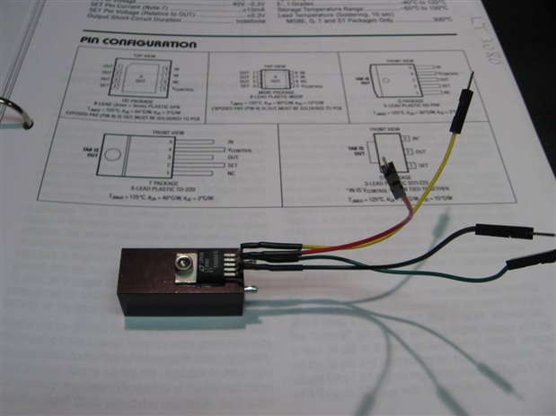
It will come as no surprise that I have labeled the leads so I do not have to keep going back to the data sheet to verify correct hookups. While this small heat sink would be inadequate for any long term high power application it is big enough for short tests and experiments. Later in the experiment you will see what I do if I feel that I need more heat sink than provided.


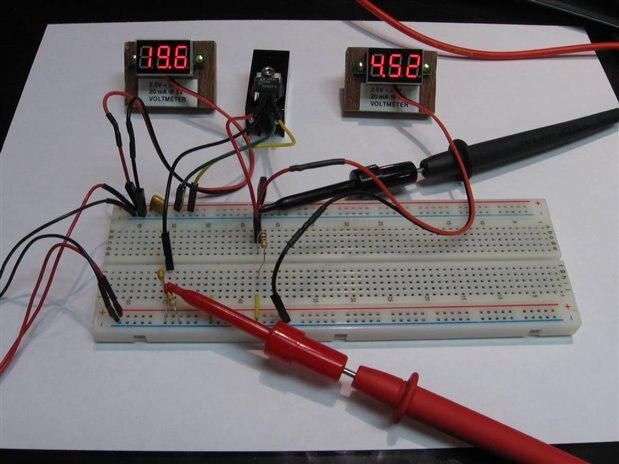
The next part of my exploration involves hooking the device up on a bread board and testing it to see if it really does what they say it will do. Here is a picture of my experimental setup:


image


Unfortunately even with good planning and a very simple experiment things can and do go wrong. Here are the difficulties that I encountered in the first three hours of experimentation.


The LT3080 did not work as advertised. It was difficult to get it to begin regulating and when it was working the slightest capacitive extra load would cause it to drop out. I could not get it to start with my electronic load attached. To add the electronic load I would first have to put the load in series with a 330 ohm resistor and then short past the resistor.


I also was experiencing a situation where the external set resistance needed to be 2 magnitudes smaller that called for by the data sheet specs in order to control the output. Measured current from the internal current source was only 10 uA at very low input voltages and it was not stable, rising with an increase in input voltage. When the regulator was actually working the current from the Set pin was very close to 1 mA.


I experimented with different voltages, resistors, decoupling capacitors, and various resistive and capacitive loads. When one is new to a component it is easy to feel that you have done something wrong so I tore the bread board down and redid it a couple times. I also searched to see if there was a different data set that applied to the TO 220 version which I had purchased compared to the smd devices.


I have learned from experience that when handled properly the problem is very seldom the IC itself, but having exhausted all the other possibilities at 2:30 AM I decided to prepare the second chip that I had purchased and to see if that one worked better or if it gave me the same problems as the first.


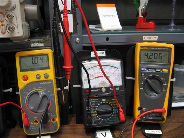
Thankfully the second LT3080 worked as advertised. This allowed me to put the experiment aside and crawl off for some sleep. This morning, all refreshed, I went back to work running my simple tests to see the limits of the regulator. During these tests the electronic load worked as intended and I was able to raise the current to the limits of the device which allowed me to see how the internal current limit would work. If you look carefully at the next picture you will see what I do when I need more heat sink as I did in these stress tests.


image


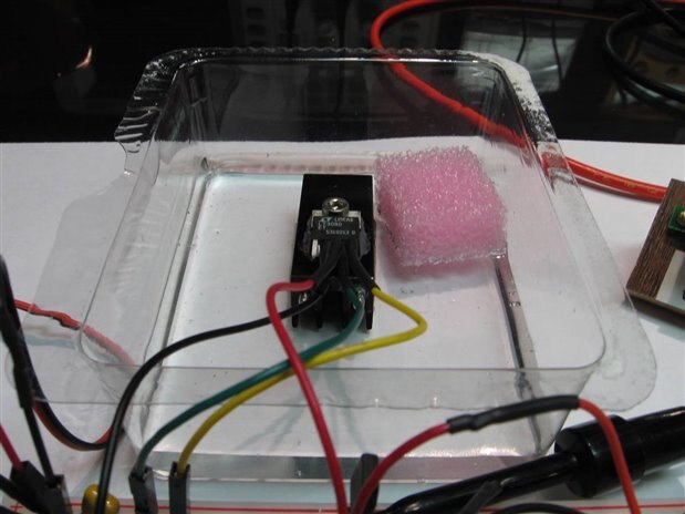
I put the Styrofoam in the water so you can see the level. In this case just enough to cover the fins of the heat sink. In the next picture you will see how I am also using a light bulb for an extra test load and the little bread board meters are monitoring the input and output voltages. The two digital bench meters are monitoring the output current and the Set pin voltage respectively.


    imageimage


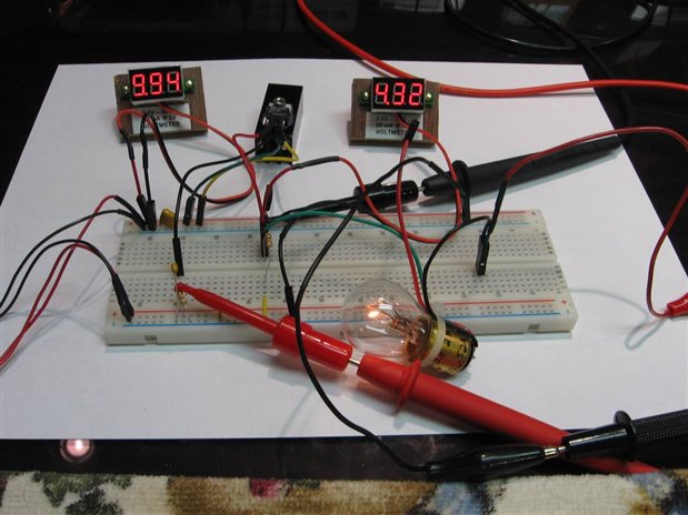
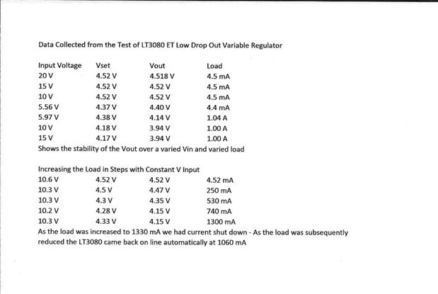
Here is the data from my tests. I was able to satisfy myself of the very good stability of the output regardless of how the input voltage or load is varied. On the output current limit I found that around 1330 mA the internal current limit would engage. This would drop the voltage output to a very low level and the current would drop to about 1000 mA as the electronic load attempted to maintain the load level. When I manually reduced the electronic load back from the 1300 mA level the LT3080 came back on line as soon as the load approached 1000 mA. Here is a simple data sheet of my measurements:


image


There are still several interesting experiments suggested by the data sheet that I will be pursuing but first I have to get a couple more LT3080s so I can try putting them in parallel and series. I also want to configure one in the LDO mode of 350 mV where the Pass Transistors collector is separate from the voltage supply to the control circuitry. All toll there are about 15 typical applications that should keep me busy for a while.

.

John

  • Sign in to reply

Top Comments

  • shabaz
    shabaz over 9 years ago +3
    Hi John, I'm glad you're experimenting with these devices! I've had my mind on these parts recently too, so it is interesting to see all your detailed findings. The paralleling capability is nice, but…
  • jc2048
    jc2048 over 9 years ago +2
    Nice example of experimenting. My vote would be for looking at the transient response next. What shabaz writes sounds very plausible as a way the device could have been damaged, but did you think to look…
  • jw0752
    jw0752 over 9 years ago +2
    FOLLOWUP - A couple additional Experiments. The first additional experiment that I wanted to do is see how well paralleling the LT3080 works. One of the limitations that must always be faced in experiments…
  • jw0752
    jw0752 over 9 years ago

    FOLLOWUP - A couple additional Experiments.


        imageimage


    The first additional experiment that I wanted to do is see how well paralleling the LT3080 works. One of the limitations that must always be faced in experiments is the limitations of the test instruments of the lab. In my case I have good confidence to the level of 10 mV, 100 uA and 10 mOhm. While this is not very good for any precision decisions it is more than adequate for the level of experimentation that I am currently doing. For this experiment I mounted a second LT 3080 as I did before but I did not have an identical heat sink so the two devices are potentially not running at the same temp. I changed my extended cooling ability by putting a small 12 V fan directly on the two devices. The ballast resistors that I used for this experiment were 100 milliohm as opposed to the 10 milliohm called for in the application sheet. This was a result of the available resources and ability to easily construct the recommended values. I also wanted to read voltages across the ballast resistors to determine the individual LT 3080 currents. The two devices performed well with a combined current load of 2.15A with one device taking 56% (1.21A) of the load and the other handling 44% (0.94A). I am certain this would level out better if I was able to lower the ballast values and equally heat sink the two devices.


         imageimage


    For this experiment I was not able to use the electronic load as it is only available as a constant current load. Therefore I am back to using the old trusty automotive tail light. Under a this load I was able to set the current from 0 to 0.41 A using the recommended set up. The application indicated a 0 to 1.0 Amp capability but I was not able to get more than 7 volts to drive the bulb with an input of 13 volts which limited my current to the measured 0.41 A. I would then vary the load slightly by adding resistors across the light bulb and observing the change in the current output. The stability of the current was acceptable for the crudeness of the breadboard set up with all its inherent variables. Available time and interest limited my pursuit of further unanswered questions at this time.


    My over all conclusion for the LT 3080 is that it is a nice flexible device that will have some applications in my future designs but it will not replace the standard 78** or the LM317 completely.


    John

    • Cancel
    • Vote Up +2 Vote Down
    • Sign in to reply
    • More
    • Cancel
  • jw0752
    jw0752 over 9 years ago in reply to jc2048

    Thanks Jon for the comprehensive reply. Your general knowledge is well presented and you have given me some excellent ideas for continuing to learn more about this component. I have been interested in electronics all my life and I have self educated most of the way. During my working years I never had the time to focus on general electronics as much as I wanted to. Now that I am retired I am focusing more and going back and trying to build a better foundational knowledge base. The experiments with individual components are just one of the tools to keep things interesting. Whether you consider yourself an expert or not is irrelevant as I can tell that I could learn a lot from you.

    Thanks John

    • Cancel
    • Vote Up 0 Vote Down
    • Sign in to reply
    • More
    • Cancel
  • jc2048
    jc2048 over 9 years ago in reply to jw0752

    It isn't a mistake to refer to it as a decoupling capacitor and it isn't just there to ensure stability. I was trying to draw your attention to the role it plays in ensuring the regulator remains stable but didn't phrase it very well (unfortunately, I'm better at using a scope than a keyboard).


    I'm not an expert in all this. I've always worked for small companies and had to be a bit of a 'Jack of all trades'. I write software, do digital design and analogue design, lay out boards, try and solve EMC problems, but wouldn't claim to be an expert in any of those and you should take that into account when reading anything that I write.


    I think that the chip designers intended you to put the output capacitor close to the regulator output pin with minimal traces to the output pin and ground. You can tell it's reasonably critical because they give you a maximum ESR value for the component and some electrolytics and a lot of tants wouldn't meet it (in this case they are also kind enough to spell it out in the notes, though you won't always see that with datasheets; Linear have always been good in that respect and you can learn a lot just by reading their datasheets, never mind the application notes).


    The reason stability is an issue is because the regulator uses feedback to maintain the output (the output voltage is compared to the reference and the pass transistor is controlled to adjust the output) and anywhere where you have feedback you can also have oscillation if you get it wrong. Why LDO regulators tend to be sensitive in this way (putting quite stringent constraints on the output capacitors), when other regulators are unconditionally stable and you can do what you like with them, I've got no idea - I think you'd have to talk to a chip designer to find that out.


    In your case, where you are using a ceramic capacitor with an ESR of a few mOhms, you'll easily meet the spec, but it's still not a good idea to have it at the end of long wires.


    Are you aware that capacitors have a self-resonant frequency? That's the frequency where the capacitance is matched by the parasitic inductance of the leads and the whole thing no longer looks like a capacitor. It's an important factor to be aware of if you are looking at decoupling on high speed digital parts like FPGAs and it's surprisingly low in frequency, particularly with a leaded component (SMD parts are obviously better). [The FPGA manufacturers have application notes that go into this in great detail and are well worth a read for the general principles even if you aren't going to be laying out FPGA boards.]


    You are thinking of your wires as being resistive, but if you wanted to model them (very, very roughly for a spice simulation) you'd probably choose an inductor in series with a resistor. They are inductive because when you pass a current through them it forms a magnetic field around the wire [I vaguely remember from school physics classes - a long time ago now - how you hold out your thumb in the direction of the current and the curl of your fingers shows the direction of the magnetic lines of force, though which hand you use I don't remember]. Your wires dramatically increase the length of the leads of the component, and hence their inductance, and will result in that self-resonant frequency decreasing. If the feedback loop still has gain up towards that frequency than you've got a real problem. Whether you really do have a problem I can't say because I have no information about the insides of the chip, but a good rule in electronic design is to not needlessly make problems for yourself.


    One final thought. The Linear website says that they have a spice model for the part so it might be interesting to try a bit of virtual breadboarding with LT Spice and see what that has to say if you built a spice model with the wire parasitic inductances and resistances included in series with the capacitor (and it's ESR resistance) on the output. Be a bit cautious with it, though, because their model won't be a physical model (it won't model all the internal components because they won't want to give away that info to their competitors) but rather will be an equivalent that behaves in a way that reasonably matches the parts in normal use, but not necessarily match if you push it to extremes (like trying to turn it into an oscillator).


    Final, final thought. Perhaps element14 could have a word with Linear Technology and see if they'd be willing to donate [or loan] a reference board so that you could do these experiments in a more controlled way. They seem to have one that has 4 of the devices in parallel on it, which I imagine would really interest you.

    • Cancel
    • Vote Up +1 Vote Down
    • Sign in to reply
    • More
    • Cancel
  • jw0752
    jw0752 over 9 years ago in reply to jc2048

    Hi Jon,

    I really appreciate your accurate and insightful observations. This type of comment is valuable to me as a learning tool and it is also valuable to those who are just learning about electronics as it brought to light a couple of the side effects of my process. While the bread board wires are very convenient they are too long and actually have a non-trivial resistance. I have had problems in the past in critical designs where the bread board wires became a troublesome factor. If I were to work more often with these 5 legged TO 220 devices I think I would build an adapter that tied the leads more directly to the bread board. The load resistor that I used was a 1K so there should have been sufficient load on the Vout. This was one of the first things that I tried adjusting when I began to have problems and in fact my defective part did work better under an increased load. Your point about using the scope to look at the Output, especially when I was having problems, is well taken. I spent most of my 55 years in electronics without the aid of a scope so I do not use it like I should. I have a great little 2 channel 100 MHz scope so there is really no excuse. Finally I wanted to expand on your observation that the output capacitor that I mistakenly called a "Decoupling Capacitor" is just for stabilization. If you could clarify for me the difference it would be appreciated and might give me more insight into the operation of this LT3080. I have requested contact with you because your comment to me was written so well that I think your continuing valuable participation on this web site will be appreciated by me and many others. I look forward to following your posts and comments.

    John

    • Cancel
    • Vote Up 0 Vote Down
    • Sign in to reply
    • More
    • Cancel
  • jw0752
    jw0752 over 9 years ago in reply to shabaz

    Hi Shabaz,

    For me the best part of my blogs is the excellent advice and insights I get when you guys comment. Thank you for pointing out that they want 10 mOhm on the outputs for ballast. I might have missed this as sometimes I get so excited to try an experiment that I make assumptions with consequences. The cause of the failure of my first part was likely me and it could have been n accidental over voltage across the Set to Vout that exceeded 0.3 V. With respect to the back to back schottky diodes from Vout to Set I got the impression they were an integral part of the IC. ( See Note 7 on page 4) I also saw no other indication that adding these diodes externally was a recommended option. I am still getting my skill set for reading and interpreting Data Sheets so I wouldn't be surprised if I got this wrong. I will take a look at the LT3081 the next time I order parts. For now I better finish this project with the LT3080 before I over extend. Thanks again for your help.

    John

    • Cancel
    • Vote Up 0 Vote Down
    • Sign in to reply
    • More
    • Cancel
>
element14 Community

element14 is the first online community specifically for engineers. Connect with your peers and get expert answers to your questions.

  • Members
  • Learn
  • Technologies
  • Challenges & Projects
  • Products
  • Store
  • About Us
  • Feedback & Support
  • FAQs
  • Terms of Use
  • Privacy Policy
  • Legal and Copyright Notices
  • Sitemap
  • Cookies

An Avnet Company © 2025 Premier Farnell Limited. All Rights Reserved.

Premier Farnell Ltd, registered in England and Wales (no 00876412), registered office: Farnell House, Forge Lane, Leeds LS12 2NE.

ICP 备案号 10220084.

Follow element14

  • X
  • Facebook
  • linkedin
  • YouTube