


Last night for the fun of it I disassembled a couple of circuit boards like this one:

I am not sure of their function but they seem to be a small receiver that is controlling 2 SPDT Relays whose switch contacts exit on the pins. I have about a dozen of them and the small project box and salvage components looked like a good collection of parts. After they were disassembled I began to ID the parts and among the regular things I found a 3 lead TO92 component marked 7039A-1. A little research on the web and I was able to fully identify it as a Holtek HT7039A-1 TinyPower Voltage Detector.
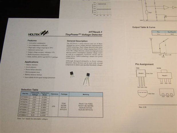
Not having ever seen or worked with a Voltage Detector before I decided to hold it out from stock for further investigation and a little experimenting. I learned that the "39" in the part number designated a device set to detect 3.9 volts. Here is a simplified schematic of the internal architecture:

According to the data sheet the voltage between VDD and VSS can be 0 volts to 30 volts. The HT7039A-1 senses this voltage and responds in the following manner. If VDD is increasing and becomes greater than the 3.9 volt specification the open drain output goes high. As VDD is decreasing from above 3.9 volts the open drain output goes low at 3.9 volts. There is a nominal 195 mV window of hysteresis according to the data sheet.
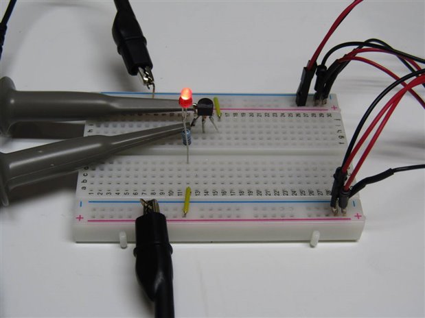
For my first experiment I set up a simple bread board circuit using an LED with a 1K series resistor as a load for the open drain on pin 1. I powered this with a 5 volt source. This is a low power device and can typically sink 4 mA. Using a separate power supply I varied the voltage between VDD and GND. It was noted that as the voltage from the supply was increasing the light turned on as soon as VDD was above 1 volt and abruptly turned off when the voltage on VDD exceeded 4 volts. The light stayed off as the voltage on VDD was increased and while specs said I could go to 30 volts I stopped at 12 volts and began to decrease the voltage. As I came to 3.9 volts the LED again lit. The voltages observed were being read from the power supply which isn't very accurate.
For the next experiment the signal generator was set to 1Hz with a 1 volt PP sine output on top of a 3.7 volt dc offset. This would be the source of VDD and would supply the VDD with from 3.2 volts to 4.2 volts. Channel one of the oscilloscope was monitoring this signal on VDD while channel two of the oscilloscope was monitoring the Output of the 7039 which was still tied to the LED, 1 K series resistor and supplied with 5 volts.
Here is a picture of the scope screen with this experiment in progress:
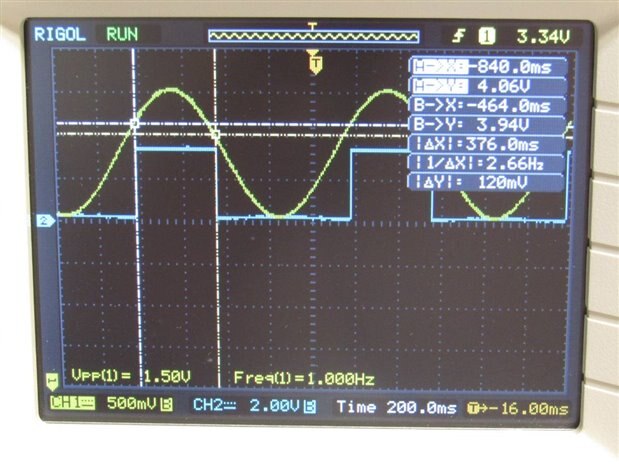
I have used the oscilloscopes cursors to find the VDD voltage at the points where the output goes high and low. On the rising side the output goes high at 4.06 Volts and the LED turns off. On the falling side the output goes low at 3.94 volts and the LED turns on. The difference between the on and off points should be the hysteresis width. In the case of our measurements this is 120 mV. The data sheet specified a width of 195 mV so we are close to specifications.
The data sheet suggests several applications for this circuit including Microcomputer Reset Circuit, Power On Reset Circuit, Power Line Monitor, and Charge Monitor Circuit. Additional information on the data sheet indicated that resistive voltage dividers can be used to adjust the sensing point from the fixed points like the 3.9 volts of this device if needed. I will attach a pdf of the data sheet in case I have tweaked your curiosity.
John
| HT7039A-1 Voltage Detector.pdf |

Top Comments